Chat Live
 Contact Us
 sales@valuetronics.com


This product generates high voltage! The use of this product requires knowledge of electricity. Improper handling or operation of this product can be very dangerous, so be sure to read the instruction manual carefully and use this product properly.

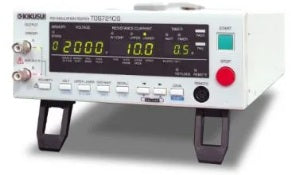
The PID insulation tester (TOS7210S) is designed based on the insulation resistance tester (TOS7200) to carry out the evaluation of the PID (Potential Induced Degradation) effect of the PV module precisely and efficiently. Being equipped with the output ability of 2000V and the ammeter with nA resolution as well as a polarity switching function, the TOS7210S is also applicable not only to the PID evaluation but also the evaluation of the insulators that requires a high sensitivity of measurement. The tester is equipped with the panel memory that is externally accessible and RS232C interface as standard; it can be flexibly compatible with the automated system.
The PID effect is a phenomenon that the amount of power generation by a cell remarkably decreases when high voltage is applied between the solar cell and the frame for long hours. It is supposed that the higher the applied voltage is and/or the higher and more humid the environment is, the further deterioration accelerates. For example, the potential difference in the string becomes extremely higher when the number of sheets that are connected in series increases even if the output voltage of the crystalline silicon solar cell module is just tens of volts. On the other hand, the grounding methods of the PCS (Power Conditioning System) that connects to the system as an AC power supply varies according to the type of PCS. In recent years, the transformerless method, where the input side is in the floating method (the negative polarity is not connected to the ground) is increasing. In this case, a high potential difference occurs between the cell and the ground. Regarding the crystalline silicon solar cell module, it is proved that the cell having a higher negative electric potential than that of the frame (ground) easily causes the PID effect. (See Fig. 1) The PV modules are currently managed with the maximum system of voltage as 600V in Japan and 1000V in Europe. There is a market trend that the maximum voltage of the commercial mega solar system is raised from the perspective of reducing the number of the strings and the total number of the PCS, and improving the efficiency of power generation.
![PID effect [Fig. 1]](https://kikusui.co.jp/kiku/wp-content/uploads/2025/06/TOS7210S-fig03-en.jpg)
![PID effect [Fig. 2]](https://kikusui.co.jp/kiku/wp-content/uploads/2024/11/TOS7210S-fig04-en.jpg)
Figure 2 shows the simulation of a crystalline silicon solar cell module being exposed to a high potential difference. It is considered that, in the PID effect of the crystalline silicon solar cell module, the sodium ion in the white tempered plate glass moves to the side of the cell and then causes the deterioration. (The PID ef fec t of the thin f ilm solar cell module is also confirmed, however, the mechanism of the deterioration is different from that of the crystalline silicon solar cell module.) The cause of the PID effect is currently being tested with and researched by various research organizations.
You can set the test voltage that is applied to the DUT within the range of 50 Vdc to 2000 Vdc (resolution 1V). In addition, an insulation resistance test of the electricity/electronic components or the electricity/electronic devices is also possible besides the voltage specified in JIS C 1302:1994. In the range of 50V to 1000V, the output properties are complied to JIS C 1302:1994.
You can easily change the output polarity by the switch on the front panel. The PID deterioration is a reversible phenomenon that may recover after the reverse bias voltage is applied. The polarity switching is a convenient function that can avoid a wiring change that connects to the DUT. In addition, switching by the external control through the RS232C interface is also possible.
In the resistance display mode, the voltage depending on the measured resistance is logarithmically compressed and output within the range of 0V to 4V. In the current display mode, the current is output in a linear scale depending on the measured current and ranges of measurement (4 ranges). You can analyze the changes or the deterioration status of the DUT by using an external recording device such as the data logger.
The output terminal is floating from the ground electric potential. *1 In addition, a shield cable is adopted as an output cable. Therefore, it can be measured only an electric current flowing between test points excluding the one between the DUT and the ground, and it realizes to conduct the highly-sensitive and precise evaluation.
*1: Ground voltage of the terminal that polarity is set as an anode (±1000 Vdc) Ground voltage of the terminal that polarity is set as a cathode (+1000 Vdc and -3000 Vdc)
*The image is for reference only. See product specification for details.
Model No
Kikusui
Condition
New
Manufacturer
Kikusui


30+ Years in Business

Secure Payments

Sell Test Equipments

Knowledgeable Staff

On-site Lab
30+ Years in Business
Secure Payments
Sell Test Equipments
Knowledgeable Staff
On-site Lab
Request A Quote