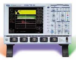
The LeCroy Waverunner-2 LT354 is a four-channel, 500 MHz digital oscilloscope and the newest member of the Waverunner-2 series. It is built to let engineers quickly view, measure, and evaluate signals accurately and reliably, combining the capture, viewing, and analysis of both simple and complex signals in one integrated system. The Waverunner-2 series was designed to save engineers valuable time in troubleshooting signals and general problem solving.
Within the series, the LT354 is aimed at capturing long, complex signals in a single shot and at tracking down timing and signal-integrity problems in high-speed designs. Tools such as JitterTrack and TrackView help trace timing and signal-integrity issues to their source, and the instrument supports the evaluation of critical timing parameters and crosstalk. Optional software packages extend it into power measurements, disk-drive and media development, wireless and network communications, and computer design.
ValueTronics has specialized in new and used test-and-measurement equipment since 1992, stocking and holding its own inventory in a 20,000 square-foot secure warehouse at 1675 Cambridge Drive in Elgin, Illinois. Because the equipment sits on our own shelves, we can stand behind what we ship: every pre-owned instrument is inspected and functionally verified in-house before it leaves the building, while new units ship factory-sealed exactly as received.
LeCroy Corporation, founded in 1964 and headquartered in Chestnut Ridge, New York, was acquired by Teledyne Technologies in 2012 and has since operated as Teledyne LeCroy.
| Specification | Value |
|---|---|
| Vertical System | |
| Input Channels | 4 |
| Analog Bandwidth @ 50 Ω (-3 dB) | 500 MHz |
| Hardware Bandwidth Limits | 20 MHz or 200 MHz |
| Input Impedance | 50 Ω ± 1%; 10 MΩ//12 pF typical (using PP006 probe) |
| Input Coupling | 1 MΩ: AC, DC, GND; 50 Ω: DC, GND |
| Maximum Input | 50 Ω: 5 Vrms; 1 MΩ: 400 Vmax (peak AC ≤5 kHz + DC) |
| Vertical Resolution | 8 bits; up to 11 bits with enhanced resolution (ERES) |
| Sensitivity (50 Ω or 1 MΩ) | 2 mV – 10 V/div fully variable |
| DC Gain Accuracy | ± (1.5% + 0.5% of full scale) |
| Offset Accuracy (50 Ω or 1 MΩ) | ± (1.5% + 0.5% of full scale + 1 mV) |
| Offset Range | 2 mV – 99 mV/div: ±1 V; 100 mV – 99 V/div: ±10 V; 1 V – 10 V/div: ±100 V |
| Isolation — Channel to Channel | >250:1 at same V/div settings |
| Timebase System | |
| Timebases | Main and up to four independent zoom traces simultaneously |
| Ranges | 500 ps/div – 1000 s/div |
| Clock Accuracy | ≤10 ppm |
| Interpolator Resolution | 5 ps |
| External Clock Frequency | 500 MHz maximum, 50 Ω, or 1 MΩ impedance |
| Roll Mode – Operating Range | time/div 500 ms – 1000 s/div or sample rate <100 kS/s max |
| External Timebase Clock | 500 MHz maximum external sample clock input on front panel EXT BNC |
| Acquisition System | |
| Maximum Single Shot Sample Rate/Ch | 1 GS/s |
| Maximum Acquisition Points – Standard | 250k |
| Maximum Acquisition Points – M-option | 1M |
| Maximum Acquisition Points – ML-option | 2M |
| Random Interleaved Sampling (RIS) | 50 GS/s for repetitive signals: 500 ps/div – 2 µs/div |
| Single Shot | For transient and repetitive signals: 500 ps/div – 100 s/div |
| Sequence – Standard | 2 – 1,000 segments |
| Sequence – Memory Option M or ML | 2 – 4,000 segments |
| Intersegment Time | 50 µsec max. |
| Acquisition Processing | |
| Averaging | Summed averaging to 103 sweeps; continuous averaging with weighting range from 1:1 to 1:1023 (standard) |
| Enhanced Resolution (ERES) | From 8.5 to 11 bits vertical resolution |
| Envelope (Extrema) | Envelope, floor, roof for up to 106 sweep |
| Triggering System | |
| Modes | Normal, Auto, Single, and Stop |
| Sources | Any input channel, external, Ext/10 or line; slope, level, and coupling unique to each source (except line trigger). Inactive channels usable as trigger inputs. |
| Slope | Positive, Negative, Window |
| Coupling modes | DC, AC, HF, HFREJ, LFREJ |
| AC Cutoff Frequency | 7.5 Hz Typical |
| HFREJ, LFREJ | 50 kHz typical |
| Pre-trigger delay | 0 – 100% of horizontal time scale |
| Post-trigger delay | 0 – 10 000 divisions |
| Hold-off by time or events | Up to 20s or from 1 to 99 999 999 events |
| Internal trigger range | ±5 div |
| Max trigger frequency | 500 MHz (with HF trigger coupling) |
| External trigger input range | ±0.5 (±5 V with Ext/10 selected) |
| Maximum ext. input @ 50 Ω | ±5 V DC or 5 Vrms |
| Maximum ext. input @ 1 MΩ | 400 Vmax (DC + peak AC < 5 kHz) |
| SMART Triggers | |
| State or Edge Qualified | Triggers on any input source only if a defined state or edge occurred on another input source. Delay between sources is selectable by time or events. |
| Dropout | Trigger if signal drops out for longer than selected time between 25 ns and 20 s. |
| Pattern | Logic combination of 5 inputs (3 on 2 channel models); Each source can be high, low, or don't care. Trigger entering or exiting the pattern |
| TV-Video | Triggers selectable fields (1, 2, 4, or 8) for NTSC, PAL SECAM, or nonstandard video (up to 1500 lines) |
| Signal or Pattern Width | Triggers on glitches or on pulse widths selectable from <2.5 ns to 20 s or on intermittent faults. |
| Signal or Pattern Interval | Triggers on intervals selectable between 10 ns and 20 s. |
| Slew Rate (optional Advanced Trigger Package) | Trigger on edge rates; select limits for dV, dt, and slope. Select edge limits between 2.5 ns and 20 s. |
| Runt (optional Advanced Trigger Package) | Positive or negative runts defined by two voltage limits and two time limits. Select between 2.5 ns and 20 ns. |
| Automatic Setup | |
| Auto Setup | Automatically sets timebase, trigger, and sensitivity to display a wide range of repetitive signals |
| Vertical Find | Automatically sets the vertical sensitivity and offset for the selected channels to display a waveform with maximum dynamic range |
| Probes | |
| Model PP006 | 10:1, 10 MΩ with auto-detect (one per channel) |
| Probe System: ProBus | Automatically detects and supports a wide variety of differential amplifiers; active, high-voltage, current, and differential probes |
| Scale Factors | Up to 12 automatically or manually selected |
| Color Waveform Display | |
| Type | VGA color 8.4" flat-panel TFT-LCD |
| Resolution | VGA 640 x 480 pixels |
| Screen Saver | Display blanks after 10 minutes (when screen saver is "on") |
| Real Time Clock | Date, hours, minutes, and seconds displayed with waveform |
| Number of Traces | Display a maximum of eight traces. Simultaneously display channel, zoom, memory, and math traces |
| Grid Styles | Single, Dual, Quad, Octal, XY, Single + XY, Dual + XY; Full Screen gives enlarged view of each style |
| Intensity Controls | Separate intensity control for grids and waveforms |
| Waveform Styles | Sample dots joined or dots only — regular or bold sample point highlighting |
| Trace Overlap Display | Select opaque or transparent mode with automatic waveform overlap management |
| Analog Persistence Display | Analog & Color-Graded Persistence: Variable saturation levels; stores each trace's persistence data in memory |
| Trace Selection | Activate Analog Persistence on a selected trace, top 2 traces, or all traces |
| Persistence Aging Time | Select from 500 ms to infinite |
| Sweeps Displayed | All accumulated or all accumulated with last trace highlighted |
| Zoom Expansion Traces | Display up to Four Zoom Traces |
| Vertical zoom | Up to 5X expansion, 50X with averaging |
| Horizontal zoom | Expand to 2 pts/div, magnify to 50,000X |
| Auto Scroll | Automatically scan and display any zoom or math trace |
| Rapid Signal Processing | |
| Processor | Power PC |
| Processing Memory | Up to 128 Mbytes |
| Realtime Clock | Dates, hours, minutes, seconds, and time stamp trigger time to 1 ns resolution |
Important: Maximum input: 50 Ω — 5 Vrms; 1 MΩ — 400 Vmax (peak AC ≤5 kHz + DC).
Recommended pairing: the LT354's ProBus system auto-detects compatible probes and amplifiers, including the HFP 1000 active probe, ADP300 series differential probes, CP/AP series current probes, and DA1800 series differential amplifiers.
This pre-owned unit is inspected and functionally verified in-house before it ships and is backed by our pre-owned warranty. To confirm its exact condition, firmware revision, installed options, or included accessories for your application before ordering, contact our Test Architects.
ValueTronics supplies both new and used test and measurement equipment. New units ship factory-sealed, exactly as received from the manufacturer; every used unit is inspected and functionally verified in-house at our 20,000 sq ft secure facility in Elgin, Illinois before it ships. Our Test Architects can help you select the condition, calibration, and configuration that fit your application.
Please review the Manufacturer's Data Sheet to verify published specifications. Feedback on this webpage is always welcome — please reach out to your Test Architect at any time for questions or concerns. Thank you, we truly appreciate you being our customer.
Model No
LeCroy
Condition
Pre-Owned
Manufacturer
LeCroy
Osc_ch
4
Osc_freq
500 MHz
Osc_r
50 Ω / 1 MΩ
Osc_sampl
1 GS/s

30+ Years in Business
Secure Payments
Sell Test Equipments
Knowledgeable Staff
On-site Lab
30+ Years in Business
Secure Payments
Sell Test Equipments
Knowledgeable Staff
On-site Lab
Request A Quote
 Chat Live
 Contact Us
 sales@valuetronics.com