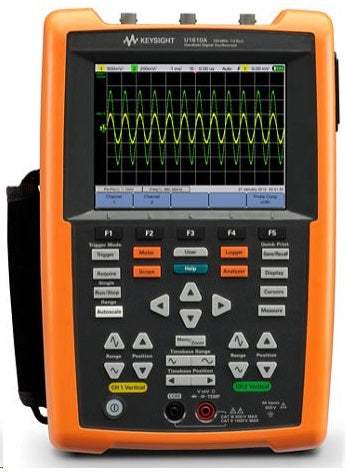
The Keysight U1610A/U1620A is a two-channel handheld digital oscilloscope built around a 5.7-inch VGA TFT LCD display and two CAT III 300 V isolated channels for floating measurements. Spanning 100 MHz and 200 MHz bandwidth models, the series combines deep acquisition memory, a fast sampling rate, and an integrated digital multimeter in a portable instrument intended for on-site and field troubleshooting.
The series captures non-repeating events such as pulse-width-modulated circuit behavior, inrush, transients, and motor start-up sequences, holding them over a wider time base for detailed review. Channel-to-channel isolation lets technicians perform floating measurements on signals referenced to different potentials, and the dual-window zoom helps identify problem areas and examine subtle waveform detail and glitches.
ValueTronics stocks and holds its own inventory in a 20,000-square-foot secure warehouse at 1675 Cambridge Drive in Elgin, Illinois, so the instruments listed here are equipment we keep on hand.
Keysight Technologies traces its test-and-measurement roots to Hewlett-Packard, whose instrument business was spun off as Agilent Technologies in 1999 and then established as Keysight Technologies in 2014.
The U1610A and U1620A make up a two-model family of handheld digital oscilloscopes that share the same VGA display, two isolated channels, integrated multimeter, and data-logging architecture. The models are distinguished primarily by bandwidth and acquisition performance: the U1610A provides 100 MHz bandwidth and the U1620A provides 200 MHz.
Both models carry CAT III 300 V isolated channels and the same 5.7-inch VGA TFT LCD with three viewing modes, so the choice between them centers on the bandwidth, sampling rate, and memory depth a given application requires rather than on feature set.
Each model below links to its own dedicated product page with new condition-matched pricing. Select the model that fits your measurement needs, then choose the available condition and configuration on that model's page.
The two models differ along several measured specifications. The U1610A offers 100 MHz bandwidth, up to 1 GSa/s in single-channel interleaved mode (500 MS/s per channel in dual-channel operation), and up to 120 Kpts record length; the U1620A offers 200 MHz bandwidth, up to 2 GSa/s single-channel interleaved (1 GS/s per channel in dual-channel operation), and up to 2 Mpts record length.
Timebase range and resolution also differ — the U1610A spans 5 ns/div to 50 s/div with 100 ps resolution, while the U1620A reaches 2 ns/div with 40 ps resolution — and calculated rise time is 3.50 ns typical on the U1610A versus 1.75 ns typical on the U1620A. The comparison table below summarizes these differences across the family.
| Model | Bandwidth | Max Sample Rate | Max Memory Depth |
|---|---|---|---|
| U1610A | 100 MHz | 1 GSa/s | 120 Kpts |
| U1620A | 200 MHz | 2 GSa/s | 2 Mpts |
Additional differences in specifications beyond the few shown above are not listed here — see each model's full specifications below.
| Specification | Value |
|---|---|
| Vertical System | |
| Bandwidth (-3 dB) | 100 MHz |
| DC vertical gain accuracy | ± 4% of full scale (full scale is equivalent to 8 div) |
| Dual cursor accuracy | ± {DC vertical gain accuracy + 0.4% full scale (~1 LSB)} = ± {4% full scale ± 0.4% full scale (~1 LSB)} |
| Analog channels | Channel 1 and Channel 2 simultaneous acquisition |
| Calculated rise time | 3.50 ns typical |
| Vertical scale | 2 mV/div to 50 V/div |
| Maximum input | CAT III 600 V (with 10:1 probe); CAT III 300 V (direct) |
| Offset (position) range | ± 4 div |
| Dynamic range | ± 8 div |
| Input impedance | 1 MΩ ± 1% ≈ 22 pF ± 3 pF |
| Coupling | DC, AC |
| Bandwidth limit | 10 kHz and 20 MHz (selectable) |
| Channel-to-channel isolation (channels at same V/div) | CAT III 300 V |
| Probes | U1560-60002 1:1 passive probe; U1561-60002 10:1 passive probe; U1562-60002 100:1 passive probe |
| Probe attenuation factors | 1x, 10x, 100x |
| Probe compensation output | 5 Vpp, 1 kHz |
| Noise peak-to-peak (typical) | 3% of full scale or 5 mVpp, whichever greater |
| DC vertical offset (position) accuracy | ± 0.1 div ± 2 mV ± 1.6% offset value |
| Single cursor accuracy | ± {DC vertical gain accuracy + DC vertical offset accuracy + 0.2% full scale (~1/2 LSB)} |
| Acquisition | |
| Maximum sampling rate – single channel operation | 1 GSa/s interleave |
| Maximum sampling rate – dual channel operation | 500 MS/s each channel |
| Maximum recording length – single channel operation | 120 Kpts interleave |
| Maximum recording length – dual channel operation | 60 Kpts each channel |
| Vertical resolution | 8 bits |
| Peak detection | > 10 ns |
| Average | Selectable from 2 to 8192 in powers-of-2 increments |
| Filter | 10 kHz and 20 MHz bandwidth limiters |
| Interpolation | (Sin x)/x |
| Horizontal System | |
| Range | 5 ns/div to 50 s/div |
| Resolution | 100 ps for 5 ns/div |
| Timebase accuracy | 25 ppm |
| Reference position | Left, center, right |
| Delay range (pre-trigger) | 1 screen width or 120 μs (whichever less) |
| Delay range (post-trigger) | 50 ms to 500 s |
| Delay resolution | 100 ps for 5 ns/div |
| Delay time measurement accuracy | Same channel: ± 0.0025% reading ± 0.17% screen width ± 60 ps; Channel-to-channel: ± 0.0025% reading ± 0.17% screen width ± 120 ps |
| Modes | Main, zoom, XY, roll |
| Horizontal pan and zoom | Dual window zoom |
| Trigger System | |
| Sources | Channel 1, Channel 2, External |
| Modes | Normal, Single, Auto |
| Types | Edge, Glitch, TV, Nth Edge, CAN, LIN |
| Autoscale | Finds or displays active channels, sets the edge trigger type on the highest numbered channel, and sets the vertical sensitivity on the scope channel timebase to display ~2 periods; requires > 10 mVpp minimum voltage, 0.5% duty cycle, and > 50 Hz minimum frequency |
| Holdoff time | 60 ns to 10 s |
| Range | ± 6 div from center of screen |
| Sensitivity | ≥ 10 mV/div: 0.5 div; < 10 mV/div: greater of 1 div or 5 mV |
| Trigger level accuracy | ± 0.6 div |
| Coupling modes | AC (~10 Hz), DC, LF-Reject (~35 kHz), HF-Reject (~35 kHz) |
| External Trigger | |
| Input impedance | 1 MΩ ≈ 10 pF |
| Maximum input | CAT III 300 V |
| Range | DC coupling: trigger level ± 5 V |
| Bandwidth | 100 kHz |
| Measurement | |
| Automatic measurements | Delay, duty cycle (+/–), fall/rise time, frequency, period, phase shift, T-max, T-min, width (+/–), amplitude, average, base, crest, cycle mean, maximum, minimum, overshoot, peak-to-peak, preshoot, standard deviation, top, Vrms (AC/DC), active/apparent/reactive power, power factor, AC current (with U1583B/1146A), DC current (with 1146A) |
| Waveform math functions | CH1 + CH2, CH1 – CH2, CH2 – CH1, CH1 × CH2, CH1/CH2, CH2/CH1, d/dt (CH1), d/dt (CH2), ∫(CH1) dt, ∫(CH2) dt, FFT |
| Cursors | Delta V: voltage difference between cursors; Delta T: time difference between cursors |
| FFT points | 1024 |
| FFT windows | Rectangular, Hamming, Hanning, Blackman-Harris, Flattop |
| Display System | |
| Display | 5.7" TFT LCD VGA Color (outdoor readable) |
| Resolution | VGA (screen area): 640 vertical by 480 horizontal |
| Control | Vectors on/off, sin x/x interpolation on/off, infinite persistence on/off, backlight intensity, color scheme, clear display |
| Real-time clock | Date and time (adjustable) |
| Language | 10 languages (selectable) |
| Built-in help system | Functional quick help displayed by pressing the [Help] button |
| Storage System | |
| Save/recall (non-volatile) | 10 setups and waveforms can be saved and recalled internally |
| Storage mode | USB 2.0 full speed host port (supports up to 4 GB USB drive); image formats: .bmp (8-bit, 24-bit) and .png (24-bit); data format: .csv |
| I/O | USB 2.0 full-speed host, USB 2.0 full-speed client |
| Printer compatibility | PCL Inkjet, PCL Laser |
| Maximum Input Voltages and Channel Isolation | |
| Input CH1 and CH2 direct (1:1 probe) | 300 V CAT III |
| Input CH1 and CH2 (1:10 probe) | 600 V CAT III, 1000 V CAT II |
| Input CH1 and CH2 (1:100 probe) | 600 V CAT II, 1000 V CAT II, 3540 V CAT I |
| Meter input | 600 V CAT III, 1000 V CAT II |
| Scope input | 300 V CAT III |
| Voltage ratings | Vrms 50–60 Hz (AC sine wave), VDC (DC applications) |
| Channel isolation (any terminal to earth ground) | 300 Vrms CAT III |
| Digital Multimeter | |
| Maximum reading | 10,000 counts with automatic polarity indication; CAT II 1000 V or CAT III 600 V |
Important: Maximum input voltage: CAT III 300 V on the direct (1:1) scope input, CAT III 600 V with a 10:1 probe; channel-to-channel and terminal-to-earth isolation rated CAT III 300 V.
Important: Warranted specifications are valid after a 30-minute warm-up period and within ± 10 °C of the last calibration temperature; all other specifications are typical.
Important: Keysight recommends using the U1586B temperature adapter for temperature measurement.
Important: AC current measurement requires the U1583B or 1146A current clamp, and DC current measurement requires the 1146A current clamp; these current probes are not part of the standard instrument and are listed under Recommended accessories.
Recommended pairing: add the Keysight U1586B temperature module for temperature measurement, or the U1583B AC current clamp to enable the AC current measurements listed in the accessories.
This is a brand-new, factory-sealed unit, supplied exactly as it arrives from the manufacturer and backed by the full manufacturer warranty. For the exact configuration, available options, included accessories, or current lead time for your application, our Test Architects can confirm the details before you order.
ValueTronics supplies both new and used test and measurement equipment. New units ship factory-sealed, exactly as received from the manufacturer; every used unit is inspected and functionally verified in-house at our 20,000 sq ft secure facility in Elgin, Illinois before it ships. Our Test Architects can help you select the condition, calibration, and configuration that fit your application.
Please review the Manufacturer's Data Sheet to verify published specifications. Feedback on this webpage is always welcome — please reach out to your Test Architect at any time for questions or concerns. Thank you, we truly appreciate you being our customer.
Model No
Keysight
Condition
Factory New
Manufacturer
Keysight Technologies
Osc_ch
2
Osc_freq
100 MHz
Osc_r
1 MΩ
Osc_sampl
2 GSa/s

30+ Years in Business
Secure Payments
Sell Test Equipments
Knowledgeable Staff
On-site Lab
30+ Years in Business
Secure Payments
Sell Test Equipments
Knowledgeable Staff
On-site Lab
Request A Quote
 Chat Live
 Contact Us
 sales@valuetronics.com