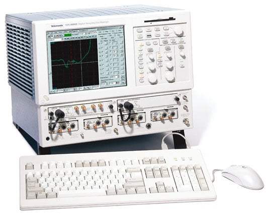
The Tektronix TDS8000B is a Digital Sampling Oscilloscope built for ultra-high-bandwidth waveform acquisition. It combines extensive on-board measurement and waveform-processing capability with strong measurement repeatability, high vertical resolution, and fast waveform acquisition and display update rates, making it a measurement tool for semiconductor testing, TDR characterization of circuit boards, IC packages and cables, and high-speed digital communications.
The instrument is applied to semiconductor testing, impedance and crosstalk characterization using TDR, and high-speed digital data communications. With its optical sampling modules it also addresses telecom signals from 155 Mb/s to 43 Gb/s and datacom standards including FibreChannel, InfiniBand, and Gigabit Ethernet, providing complete optical test solutions alongside general-purpose optical signal testing.
ValueTronics stocks and holds its inventory in a 20,000 sq ft secure warehouse at 1675 Cambridge Drive, Elgin, Illinois. Every used unit is inspected and functionally verified in-house by our technicians before shipment, while new units ship factory-sealed exactly as received — we never open or test a new instrument. Holding our own stock lets us match the right configuration to an engineer's application and ship it without delay.
The TDS8000B is part of the Tektronix 8000 Series sampling oscilloscope platform, which combines Windows-based PC technology with world-class waveform-acquisition hardware in a modular mainframe. Rather than fixing performance at the factory, the platform accepts a family of electrical and optical plug-in modules, so the same mainframe can be configured for the measurement at hand both now and in the future.
The electrical and optical sampling modules form the family that defines the instrument's reach. Electrical modules address device characterization and TDR from 12.5 GHz up to 70+ GHz, while optical modules deliver telecom and datacom conformance testing across a wide range of standard data rates.
Each pre-owned configuration is offered on its own product page with condition-matched pricing. Select the mainframe and the sampling modules that fit your bandwidth, channel-count, and optical or electrical requirements; the page you are viewing reflects the condition and pricing for that specific selection.
Within the platform, the TDS8000B pairs a multi-processor architecture and dedicated per-channel DSP with a 14-bit acquisition system, sustaining high waveform-acquisition rates regardless of the number of channels in use and supporting up to eight simultaneous automated measurements.
The modules differ primarily in bandwidth, channel count, and specialty function. Among the electrical modules, the 80E02 is a dual-channel 12.5 GHz low-noise module, the 80E03 and 80E04 are 20 GHz modules (with the 80E04 adding TDR capability), the 80E01 is a single-channel 50 GHz module, and the 80E06 is a single-channel 70+ GHz module.
Optical modules differ by wavelength range, supported data-filtering rates, and clock-recovery options, spanning tributary telecom rates through 40 Gb/s telecom and 10 Gb/s datacom standards. The comparison table that follows summarizes these per-module differences so a configuration can be matched to the target standard.
| Model | Bandwidth | Channels | Rise Time |
|---|---|---|---|
| TDS8000B | Determined by modules (DC to 70+ GHz) | 8 max | — |
| 80E01 | 50 GHz | 1 | 7 ps |
| 80E02 | 12.5 GHz | 2 | ≤28 ps |
| 80E03 | 20 GHz | 2 | ≤17.5 ps |
Additional differences in specifications beyond the few shown above are not listed here — see each model's full specifications below.
| Specification | Value |
|---|---|
| Signal Acquisition | |
| Acquisition Modes | Sample (normal), envelope and average |
| Number of Sampling Modules Accommodated | Up to four dual-channel electrical and two single-channel optical sampling modules |
| Number of Simultaneously Acquired Inputs | Eight channels maximum (eight electrical or two optical and six electrical) |
| Vertical System | |
| Rise Time/Bandwidth | Determined by the sampling modules used |
| Vertical Resolution | 14 bits over the sampling modules' dynamic range |
| Horizontal System | |
| Main and Magnification View Timebases | 1 ps/div to 5 ms/div in 1-2-5 sequence or 1 ps increments |
| Maximum Trigger Rate | 200 kHz |
| Typical Acquisition Rate | 150 Ksamples/sec. per channel |
| Time Interval Accuracy (Horizontal scale <21 ps/div) | 1 ps + 1% of interval |
| Time Interval Accuracy (Horizontal scale ≥21 ps/div, short-term optimized mode) | 8 ps + 0.1% of interval |
| Time Interval Accuracy (Horizontal scale ≥21 ps/div, locked to 10 MHz mode) | 8 ps + 0.01% of interval |
| Horizontal Deskew Range | –500 ps to +100 ns on any individual channel in 1 ps increments |
| Record Length | 20, 50, 100, 250, 500, 1000, 2000 or 4000 samples |
| Magnification Views | Two magnification views, independently acquired using separate timebase settings |
| Trigger System | |
| Trigger Sources | External direct trigger; external pre-scaled trigger; internal clock trigger (internally connected to direct trigger); clock recovery triggers from optical sampling modules (internally connected to pre-scaled trigger) |
| Trigger Sensitivity – External direct trigger input | 50 mV, DC to 4 GHz (typical); 100 mV, DC to 3 GHz (guaranteed) |
| Trigger Sensitivity – Pre-scaled trigger input | 800 mV, 2 to 3 GHz (guaranteed); 600 mV, 3 to 10 GHz (guaranteed); 1000 mV, 10 to 12.5 GHz (typical) |
| Jitter – Short-term jitter optimized mode | ≤0.8 psRMS + 5 ppm of position (typical); ≤1.2 psRMS + 10 ppm of position (max.) |
| Jitter – Locked to 10 MHz reference | 1.6 psRMS + 0.01 ppm of position (typical); ≤2.5 psRMS + 0.04 ppm of position (max.) |
| Internal Clock | Adjustable from 25 to 200 kHz (drives TDR, internal clock output and calibrator) |
| Trigger Level Range | ±1.0 V |
| Trigger Input Range | ±1.5 V |
| Trigger Holdoff | Adjustable 5 µs to 100 ms in 2 ns increments |
| External Trigger Gate (optional) | TTL logic 1 enables acquisition, TTL logic 0 disables acquisition, maximum non-destruct input level ±5 V |
| Display Features | |
| Touch Screen Display | 10.4 in. diagonal, color |
| Colors | 16,777,216 (24 bits) |
| Video Resolution | 640 horizontal by 480 vertical displayed pixels |
| Math/Measurement System | |
| Measurements | Up to eight simultaneous measurements, updated three times per second, with optional display of per-measurement statistics (min, max, mean and standard deviation) |
| Measurement Set | Automated RZ, NRZ and Pulse signal-type measurements including amplitude, timing and area measurements |
| Cursors | Dot, vertical bar and horizontal bar cursors |
| Waveform Processing | Up to eight math waveforms using Add, Subtract, Multiply, Divide, Average, Differentiate, Exponentiate, Integrate, Natural Log, Log, Magnitude, Min, Max, Square Root and Filter |
| Power Requirements | |
| Line Voltage and Frequency | 100 to 240 VAC ±10% 50/60 Hz; 115 VAC ±10% 400 Hz |
| Environmental | |
| Temperature – Operating | +10 ºC to +40 ºC |
| Temperature – Nonoperating | –22 ºC to +60 ºC |
| Relative Humidity – Operating | Floppy disk and CD ROM not installed: 20% to 80% at or below 40 ºC (upper limit de-rates to 45% RH at 40 ºC) |
| Relative Humidity – Nonoperating | 5% to 90% at or below 60 ºC (upper limit de-rates to 20% RH at +60 ºC) |
| Altitude – Operating | 3048 m (10,000 ft.) |
| Altitude – Nonoperating | 12190 m (40,000 ft.) |
| Safety | UL 3111-1, CSA-22.2 No. 1010.1, EN 61010-1 |
Important: Bandwidth is determined by the installed plug-in modules and may exceed 70 GHz as higher-speed modules become available.
Important: The TDS8000B mainframe requires one or more electrical or optical sampling modules to acquire signals; rise time and bandwidth are determined by the installed sampling modules, which are ordered separately.
Important: Clock recovery for the 80C12 optical sampling module is provided via the 80A05 Electrical Clock Recovery Module, which is sold separately.
Important: Gated triggering, which allows the exclusion of selected time periods from being measured, is offered as an option (Opt. GT).
Important: For the 80E06 module, 1 meter or 2 meter length Extender Cables (012-1568-00 / 012-1569-00) can be ordered for remote operation of the sampling module from the sampling oscilloscope mainframe.
Usage tip: pair the 80A03 TekConnect Probe Interface Module with Tektronix P7000 series probes to probe directly on IC pins, traces, or test points that are not accessible through a connector.
This pre-owned unit is inspected and functionally verified in-house before it ships and is backed by our pre-owned warranty. To confirm its exact condition, firmware revision, installed options, or included accessories for your application before ordering, contact our Test Architects.
ValueTronics supplies both new and used test and measurement equipment. New units ship factory-sealed, exactly as received from the manufacturer; every used unit is inspected and functionally verified in-house at our 20,000 sq ft secure facility in Elgin, Illinois before it ships. Our Test Architects can help you select the condition, calibration, and configuration that fit your application.
Please review the Manufacturer's Data Sheet to verify published specifications. Feedback on this webpage is always welcome — please reach out to your Test Architect at any time for questions or concerns. Thank you, we truly appreciate you being our customer.
Model No
Tektronix
Condition
Pre-Owned
Manufacturer
Tektronix
Osc_ch
8
Osc_freq
70+ GHz

30+ Years in Business
Secure Payments
Sell Test Equipments
Knowledgeable Staff
On-site Lab
30+ Years in Business
Secure Payments
Sell Test Equipments
Knowledgeable Staff
On-site Lab
Request A Quote
 Chat Live
 Contact Us
 sales@valuetronics.com