
Request a Quote To Get An EDU Discount
Couldn't load pickup availability
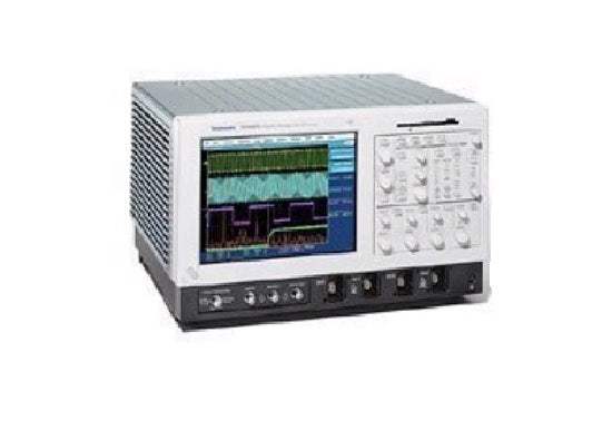
The Tektronix TDS6000 Series — comprising the TDS6604 and TDS6404 — is a family of digital storage oscilloscopes built for verification, debug, and characterization of sophisticated electronic designs. Each instrument pairs high-performance signal acquisition with classic analog-style controls, a large touch-sensitive display, and graphical menus, while open access to the Windows operating system enables customization and extensibility.
A digital storage oscilloscope captures fast electrical signals and displays them as voltage-versus-time waveforms, letting an engineer examine amplitude, timing, and signal shape. The TDS6000 Series is applied to the validation and characterization of high-speed digital designs, jitter and timing analysis, and the investigation of transient phenomena. Compliance mask tests support a wide range of computer and datacom standards, and a 32-bit serial trigger isolates pattern-dependent effects.
ValueTronics stocks and holds its own inventory in a 20,000 square-foot secure warehouse at 1675 Cambridge Drive in Elgin, Illinois. Every used unit we sell is inspected and functionally verified in-house before it ships, while new units ship factory-sealed exactly as received from the manufacturer. Operating since 1992, we match the right instrument and condition to each customer's application.
The Tektronix TDS6000 Series brings high-performance signal acquisition, operational ease, and open connectivity to the verification, debug, and characterization of sophisticated electronic designs. The family is built around exceptional acquisition and trigger performance, a touch-sensitive interface, and an open Windows environment shared across its models.
Within the series, the TDS6604 and TDS6404 share the same four-channel architecture, 20 GS/s sample rate on one or two channels, display, and connectivity, differing principally in analog bandwidth and rise time.
Each model in the series is offered below as its own dedicated pre-owned product page with condition-matched pricing. Select the bandwidth tier that fits your application, then choose the pre-owned listing for that specific model.
The two models are distinguished by their bandwidth tiers: the TDS6604 provides 6 GHz analog bandwidth with a typical rise time of 70 ps, while the TDS6404 provides 4 GHz bandwidth with a 100 ps typical rise time. Channel isolation is specified to ≥20:1 at each model's full bandwidth — 6 GHz for the TDS6604 and 4 GHz for the TDS6404. The comparison table below summarizes these per-model figures.
Beyond bandwidth and rise time, the models share their core capabilities — four input channels, 20 GS/s real-time sampling on one or two channels, 10 GS/s on four channels, identical acquisition modes, and the same Windows-based analysis and networking platform. Each also ships with a different probe calibration and deskew fixture matched to the model (067-0484-xx for the TDS6604, 067-0405-xx for the TDS6404).
| Model | Bandwidth | Rise Time | Max Real-time Sample Rate |
|---|---|---|---|
| TDS6404 | 4 GHz | 100 ps | 20 GS/s |
| TDS6604 | 6 GHz | 70 ps | 20 GS/s |
Additional differences in specifications beyond the few shown above are not listed here — see each model's full specifications below.
| Specification | Value |
|---|---|
| Vertical System | |
| Rise Time (typical) | 100 ps |
| Input Channels | 4 |
| Analog Bandwidth (-3 dB) | 4 GHz |
| Input Impedance | 50 Ω ± 2.5% |
| Input Sensitivity, 50 Ω | 10 mV/div to 1 V/div |
| Vertical Resolution | 8-Bit (> 11-Bit w/ averaging) |
| Max. Input Voltage, 50 Ω | Determined by TekConnect accessory |
| DC Gain Accuracy | 2.5% |
| Offset Range | 10 mV to 50 mV/div ± 0.5 V; 50.5 mV to 100 mV ± 0.25 V; 101 mV to 500 mV ± 5 V; 505 mV to 1 V/div ± 2.5 V |
| Channel Isolation | ≥20:1 at 4 GHz; ≥80:1 at 1.5 GHz |
| Timebase System | |
| Timebase Range | 50 ps to 10 s/div |
| Timebase Delay Time Range | 16 ns to 250 s |
| Channel-to-Channel Deskew Range | ± 25 ns |
| ∆Time Measurement Accuracy | (0.06/sample rate) + (2.5 ppm *|reading|)RMS |
| Trigger Jitter (RMS) | 7 psRMS |
| Long Term Sample Rate and Delay Time Accuracy | ± 2.5 ppm over ≥100 ms interval |
| Acquisition System | |
| Equivalent Time Sample Rate (max.) | 1,000 GS/s |
| Real-time Sample Rate, 1 channel | 20 GS/s, Record Length 250 k |
| Real-time Sample Rate, 2 channels (channel 1 with 3, channel 1 with 4, channel 2 with 3 or channel 2 with 4) | 20 GS/s, Record Length 250 k |
| Real-time Sample Rate, 2 channels (channel 1 with 2 or channel 3 with 4) | 10 GS/s, Record Length 125 k |
| Real-time Sample Rate, 3 or 4 channels | 10 GS/s, Record Length 125 k |
| Acquisition Modes | |
| Sample | Acquire sampled values |
| Peak Detect | Captures narrow glitches at all real-time sampling rates |
| Minimum Peak Detect Pulse Width | 50 ps |
| Averaging | From 2 to 10,000 waveforms included in average |
| Envelope | From 2 to 2x10⁹ waveforms included in min-max envelope |
| Hi-res | Real-time boxcar averaging reduces random noise and increases resolution |
| Trigger System | |
| Sensitivity, Internal DC Coupled | 0.35 div DC to 50 MHz increasing to 1.5 div at 3 GHz (guaranteed); 2.5 div at 4 GHz (typical) |
| Sensitivity, External (auxiliary input) | 250 mV from DC to 50 MHz increasing to 350 mV at 500 MHz |
| Main Trigger Modes | Auto, Normal and Single |
| Trigger Sequences | Main, Delayed by Time, Delayed by Events. All sequences can include separate horizontal delay after the trigger event to position the acquisition window in time |
| Trigger Level Range, Internal | ± 12 divisions from center of screen |
| Trigger Level Range, External (auxiliary input) | ± 8 V |
| Trigger Level Range, Line | Fixed at 0 V |
| Trigger Coupling | DC, AC (attenuate < 60 Hz), HF Rej (attenuate > 30 kHz), LF Rej (attenuates < 80 kHz), Noise Reject (reduce sensitivity) |
| Trigger Holdoff Range | 250 ns minimum to 12 seconds maximum |
| Edge Trigger | Positive or negative slope on any channel or front panel auxiliary input. Coupling includes DC, AC, noise reject, HF reject and LF reject |
| Glitch Trigger | Trigger on or reject glitches of positive, negative, or either polarity. Minimum glitch width is 1.0 ns with 200 ps resolution |
| Width Trigger | Trigger on width of positive or negative pulse either within or out of selectable time limits (1 ns to 1 s) |
| Runt Trigger | Trigger on a pulse that crosses one threshold but fails to cross a second threshold before crossing the first again. Optional time qualification |
| Timeout Trigger | Trigger on an event that remains high, low, or either, for a specified time period, selectable from 1 ns to 1 s with 200 ps resolution |
| Transition Trigger | Trigger on pulse edge rates that are faster or slower than specified. Slope may be positive, negative or either |
| Setup/Hold Trigger | Trigger on violations of both setup time and hold time between clock and data present on any two input channels |
| Pattern Trigger | Trigger when pattern goes false or stays true for specified period of time. Pattern (AND, OR, NAND, NOR) specified for four input channels defined as HIGH, LOW or Don't Care |
| State Trigger | Any logical pattern of channels (1, 2, 3) clocked by edge on channel 4. Trigger on rising or falling clock edge |
| Optional Communications Trigger | Support for AMI, HDB3, BnZS, CMI, MLT3, and NRZ encoded communications signals. Select among isolated positive or negative one, zero pulse form or eye patterns as applicable to standard |
| Optional Serial Pattern Trigger | 32-Bit serial word recognizer to 1.25 GBaud |
| Trigger Delay by Time | 16 ns to 250 seconds |
| Trigger Delay by Events | 1 to 10,000,000 Events |
| Waveform Measurements | |
| Amplitude | Amplitude, High, Low, Maximum, Minimum, Peak-to-peak, Mean, Cycle Mean, RMS, Cycle RMS, Positive Overshoot, Negative Overshoot |
| Time | Rise time, Fall time, Positive Width, Negative Width, Positive Duty Cycle, Negative Duty Cycle, Period, Frequency, Delay |
| Combination | Area, Cycle Area, Phase, Burst Width |
| Histogram-related | Waveform count, Hits in box, Peak hits, Median, Maximum, Minimum, Peak-to-peak, Mean (µ), Standard Deviation (σ), µ + 1σ, µ + 2σ, µ + 3σ |
| Eye-pattern Related | Extinction Ratio (absolute, %, and dB), Eye Height, Eye Top, Eye Base, Eye Width, Crossing %, Jitter (peak-to-peak, RMS, and 6σ), Noise (peak-to-peak and RMS), S/N ratio, Cycle distortion, Q-factor |
| Waveform Processing/Math | |
| Algebraic Expressions | Define extensive algebraic expressions including waveforms, scalars and results of parametric measurements e.g., (Integral (Ch1-Mean(Ch1))*1.414) |
| Arithmetic | Add, subtract, multiply, divide waveforms and scalars |
| Calculus | Integrate, differentiate |
| Frequency Domain Functions | Spectral magnitude and phase, real and imaginary spectra |
| Vertical Units | Magnitude: Linear, dB, dBm; Phase: degrees, radians |
| Window Functions | Rectangular, Hamming, Hanning, Kaiser-Bessel, Blackman-Harris, Gaussian, Flattop2, Tek Exponential |
| Waveform Definition | As arbitrary math expressions |
| Display Characteristics | |
| Display Type | Liquid crystal active-matrix color display |
| Display Size | 211.2 mm (W) x 158.4 mm (H), 264 mm (10.4 in.) diagonal |
| Display Resolution | 640 horizontal x 480 vertical pixels |
Important: Probes are not included in the price and should be ordered separately.
Important: Please specify power plug when ordering (power plug options: Opt. A0 US, A1 Euro, A2 UK, A3 Australian, A5 Swiss, A99 No Power Cord, AC China).
Usage tip: pair the oscilloscope with the Tektronix P7260 6 GHz active probe for full bandwidth at the probe tip, or the P7350 5 GHz differential probe for low-voltage differential signaling (LVDS) applications.
This pre-owned unit is inspected and functionally verified in-house before it ships and is backed by our pre-owned warranty. To confirm its exact condition, firmware revision, installed options, or included accessories for your application before ordering, contact our Test Architects.
ValueTronics supplies both new and used test and measurement equipment. New units ship factory-sealed, exactly as received from the manufacturer; every used unit is inspected and functionally verified in-house at our 20,000 sq ft secure facility in Elgin, Illinois before it ships. Our Test Architects can help you select the condition, calibration, and configuration that fit your application.
Please review the Manufacturer's Data Sheet to verify published specifications. Feedback on this webpage is always welcome — please reach out to your Test Architect at any time for questions or concerns. Thank you, we truly appreciate you being our customer.
Model No
Tektronix
Condition
Pre-Owned
Manufacturer
Tektronix
Osc_ch
4
Osc_freq
4 GHz
Osc_r
50 Ω
Osc_sampl
20 GS/s
P7240 Tektronix Active Probe Used
P7240
P7330 Tektronix Differential Probe Used
P7330
P7350 Tektronix Differential Probe Used
P7350

30+ Years in Business
Secure Payments
Sell Test Equipments
Knowledgeable Staff
On-site Lab
30+ Years in Business
Secure Payments
Sell Test Equipments
Knowledgeable Staff
On-site Lab
Request A Quote
 Chat Live
 Contact Us
 sales@valuetronics.com


