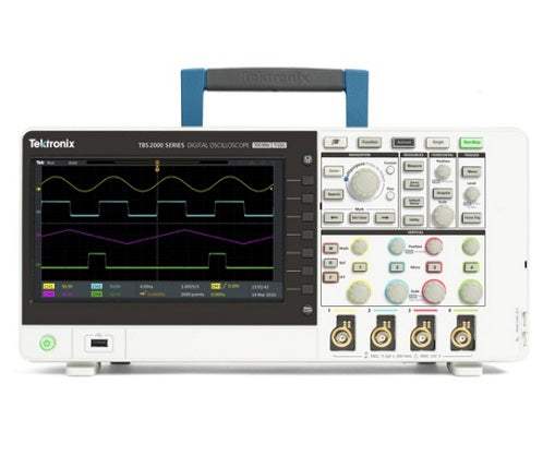
The TBS2000 Series is a family of digital storage oscilloscopes built around a 9-inch WVGA display, a 20 million point record length, and a 1 GS/s sample rate, capturing and displaying more signal to help engineers evaluate designs faster. On-waveform cursor readouts and 32 automated measurements—each accompanied by informative on-screen tips—make it straightforward to analyze signals and choose the right measurement. The TekVPI probe interface works with traditional BNC connections while also enabling the latest active voltage and current probes for wide application coverage.
An oscilloscope displays electrical signals as waveforms—voltage plotted against time—making it one of the most universal diagnostic instruments on an electronics bench. The TBS2000 Series trigger system is designed for troubleshooting mixed-signal designs, and the long record length helps find signal anomalies and verify digital communications. The series also targets education: the Courseware function lets professors load lab exercises onto the instrument to guide students at each station, and the oscilloscope integrates with the TekSmartLab lab management system so instructors can preset a lab full of instruments and track every student's progress from a central workstation.
ValueTronics stocks and holds its own inventory in a 20,000 square foot secure warehouse at 1675 Cambridge Drive in Elgin, Illinois, giving customers a single dependable source for both new and used test and measurement equipment. Every used unit is inspected and functionally verified in-house before it ships, while new units ship factory-sealed exactly as received from the manufacturer.
Tektronix, founded in 1946, has operated continuously under its own name. It was acquired by Danaher Corporation in 2007 and became part of Fortive Corporation when Fortive was spun off from Danaher in 2016.
The TBS2000 Series comprises four digital storage oscilloscope models that share the same core architecture—a 1 GS/s sample rate, a 20 M point record length on all channels, and a 9-inch WVGA display—while differing in two dimensions: analog bandwidth and channel count. The series is offered in 70 MHz and 100 MHz bandwidth models and in 2- and 4-channel configurations.
Because the acquisition system, display, triggering, measurement set, and TekVPI probe interface are common to every model, the choice between members of the family comes down to the bandwidth and channel count an application requires rather than differences in feature set.
Each model in the family below is its own dedicated product page with condition-matched pricing. Select the model that fits your bandwidth and channel requirements, then choose the pre-owned listing that matches your budget and condition preference.
The four models divide along bandwidth and channel count: the 70 MHz and 100 MHz options set the analog bandwidth, while the 2-channel and 4-channel options set how many signals can be observed at once. All four retain the 1 GS/s sample rate and 20 M point record length, so those specifications do not differentiate the models.
Physical size tracks channel count as well: the 2-channel models share one chassis footprint and weight (2.62 kg standalone) while the 4-channel models are larger and heavier (4.17 kg standalone). The comparison table below lays out bandwidth, channel count, and dimensions for each model so the right configuration is easy to identify.
| Model | Bandwidth | Analog Channels | Sample Rate |
|---|---|---|---|
| TBS2102 | 100 MHz | 2 | 1 GS/s |
| TBS2072 | 70 MHz | 2 | 1 GS/s |
| TBS2074 | 70 MHz | 4 | 1 GS/s |
| TBS2104 | 100 MHz | 4 | 1 GS/s |
Additional differences in specifications beyond the few shown above are not listed here — see each model's full specifications below.
| Specification | Value |
|---|---|
| Model Overview | |
| Analog channels | 2 |
| Bandwidth | 100 MHz |
| Sample rate | 1 GS/s |
| Record length | 20 M points |
| Vertical System (Analog Channels) | |
| Hardware bandwidth limits | 20 MHz, typical |
| Input coupling | DC, AC, or GND |
| Input impedance | 1 MΩ ± 2 %, 11.5 pF ± 2.5 pF |
| Input sensitivity range | 2 mV/Div to 5 V/Div |
| Vertical resolution | 8 bits |
| Maximum input voltage, 1 MΩ | 300 V RMS with peaks ≤ ±450 V |
| DC balance | ± (1 mV +0.1 div) |
| DC gain accuracy | ± 3% 10 mV/div through 5 V/div; ± 4% typical 2 mV/div and 5 mV/div |
| DC voltage measurement accuracy (average mode, average of 16 waveforms) | ±((DC Gain Accuracy) X |reading - (offset - position)| + Offset Accuracy + 0.11 div + 1 mV) |
| Delta Volts between any two averages of ≥16 waveforms acquired with the same oscilloscope setup and ambient conditions | ±(DC Gain Accuracy X |reading| + 0.08 div + 1.4 mV) |
| Vertical position range | ± 5 divisions |
| Vertical offset range, 2 mV/div to 200 mV/div, 1 MΩ | ± 0.8 V |
| Vertical offset range, > 200 mV/div to 5 V/div, 1 MΩ | ± 20 V |
| Analog bandwidth, DC coupled | DC to ≥100 MHz for 2 mV/div through 5 V/div. |
| Common mode rejection ratio (CMRR), typical | 100:1 at 60 Hz, reducing to 10:1 with 50 MHz sine wave with equal Volts/div and coupling settings on each channel. |
| Channel-to-channel isolation | ≥100:1 at ≤100 MHz |
| Acquisition Modes | |
| Sample | Acquire sampled values. |
| Peak Detect | Captures glitches as narrow as 3.5 ns at all sweep speeds. |
| Average | From 2 to 512 waveforms included in average. |
| Hi-Res | Averages multiple sample of one acquisition interval into one waveform point. |
| Roll | Scrolls waveforms right to left across the screen at sweep speeds slower than or equal to 40 ms/div (400 ms/div at 20M record length). |
| Math Modes | |
| Math functions | Ch 1 - Ch 2, Ch 2 - Ch 1, Ch 1 + Ch 2, Ch 1 X Ch 2, FFT |
| Horizontal System (Analog Channels) | |
| Maximum duration of time captured at highest sample rate (all channels) | 40 ms |
| Time base range | 2 ns/div to 100 sec/div |
| Time-base delay time range | -15 divisions to 5000 s |
| Deskew range | ±100 ns |
| Time base accuracy | ±25 ppm over any ≥1 ms interval |
| Trigger System | |
| Trigger modes | Auto, Normal, and Single |
| Trigger holdoff range | 20 ns to 8 s |
| Trigger type: Edge | Positive or negative slope on any channel. Coupling includes DC, HF reject, LF reject, and noise reject. |
| Trigger type: Pulse width | Trigger on width of positive or negative pulses that are >, <, =, or ≠ a specified period of time. |
| Trigger type: Runt | Trigger on a pulse that crosses one threshold but fails to cross a second threshold before crossing the first again. |
| Trigger coupling (analog channels) | DC, Noise Reject, High Freq Reject, Low Freq Reject. |
| Sensitivity, edge-type trigger, DC coupled (analog inputs) | 0.4 division from DC to 50 MHz; 0.6 divisions >50 MHz to 100 MHz |
| Trigger level ranges | Input channels: ± 4.90 divisions from center screen |
| Data Storage | |
| Nonvolatile memory retention time, typical | No time limit for Front Panel Settings, saved waveforms, setups, and calibration constants. |
| Real-Time clock | A programmable clock providing time in years, months, days, hours, minutes, and seconds. |
| Waveform Measurements | |
| Cursors | Time, amplitude and screen. |
| Automated measurements | 32, of which up to six can be displayed on-screen at any one time. Measurements include: Period, Frequency, Rise Time, Fall Time, Positive Duty Cycle, Negative Duty Cycle, Positive Pulse Width, Negative Pulse Width, Burst Width, Phase, Positive Overshoot, Negative Overshoot, Peak to Peak, Amplitude, High, Low, Max, Min, Mean, Cycle Mean, RMS, Cycle RMS, Positive Pulse Count, Negative Pulse Count, Rising Edge Count, Falling Edge Count, Area, Cycle Area, Delay FR, Delay FF, Delay FR, and Delay RR. |
| Gating | Isolate the specific occurrence within an acquisition to take measurements on, using either the screen, between waveform cursors or full record length. |
| Waveform Math | |
| Arithmetic | Add, subtract, and multiply waveforms. |
| FFT | Spectral magnitude. Set FFT Vertical Scale to Linear RMS or dBV RMS, and FFT Window to Rectangular, Hamming, Hanning, or Blackman-Harris. |
| Remote Control Software | |
| LXI web page | LXI Core 2011. Built-in web page enables remote control of horizontal and vertical scale, trigger settings, and measurements. Allows waveform and image save to USB flash drive. |
| Display System | |
| Display type | 9 inch (228 mm) wide format liquid crystal TFT color display. |
| Display resolution | 800 horizontal by 480 vertical displayed pixels (WVGA). |
| Waveform styles | Vectors, Variable Persistence, and Infinite Persistence. |
| Graticules | Grid, None. |
| Format | YT and XY. |
| Input Output Ports | |
| USB 2.0 high-speed host port | Supports USB mass storage devices, Wi-Fi dongle. One port available on rear panel and one on front panel. |
| USB 2.0 high-speed device port | Rear-panel connector allows for communication/control of oscilloscope through USBTMC or GPIB with a TEK-USB-488. |
| Compatible USB-WIFI dongles | TEK-USB-WIFI accessory; TP-LINK TL-WN823N, NETGEAR WNA1000M, WNA3100M |
| LAN port (Ethernet) | RJ-45 connector, supports 10/100BASE-T. |
| Probe compensator | Amplitude 5 V, Frequency 1 kHz |
| Kensington-style lock | Rear-panel security slot connects to standard Kensington-style lock. |
Important: Maximum input voltage (1 MΩ): 300 V RMS with peaks ≤ ±450 V.
Important: A Wi-Fi adapter is available in some countries from Tektronix distributors as an accessory, model TEK-USB-WIFI. See Ordering Information for details.
Important: Cooling clearance: 50 mm (2 in) is required on the left side and rear of the instrument.
Usage tip: add the TEK-USB-WIFI dongle to enable the series' wireless communications, or the TEK-USB-488 GPIB-to-USB adapter for GPIB instrument control.
This pre-owned unit is inspected and functionally verified in-house before it ships and is backed by our pre-owned warranty. To confirm its exact condition, firmware revision, installed options, or included accessories for your application before ordering, contact our Test Architects.
ValueTronics supplies both new and used test and measurement equipment. New units ship factory-sealed, exactly as received from the manufacturer; every used unit is inspected and functionally verified in-house at our 20,000 sq ft secure facility in Elgin, Illinois before it ships. Our Test Architects can help you select the condition, calibration, and configuration that fit your application.
Please review the Manufacturer's Data Sheet to verify published specifications. Feedback on this webpage is always welcome — please reach out to your Test Architect at any time for questions or concerns. Thank you, we truly appreciate you being our customer.
Model No
Tektronix
Condition
Pre-Owned
Manufacturer
Tektronix
Osc_ch
2
Osc_freq
100 MHz
Osc_r
1 MΩ
Osc_sampl
1 GS/s

30+ Years in Business
Secure Payments
Sell Test Equipments
Knowledgeable Staff
On-site Lab
30+ Years in Business
Secure Payments
Sell Test Equipments
Knowledgeable Staff
On-site Lab
Request A Quote
 Chat Live
 Contact Us
 sales@valuetronics.com