🎓 Request a Quote To Get An EDU Discount
Couldn't load pickup availability
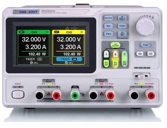
In summary, the Siglent SPD3303X is a three-channel linear DC power supply with two fully isolated 0-32 V / 0-3.2 A programmable channels (Channel 1 and Channel 2) and a fixed selectable 2.5 V / 3.3 V / 5 V auxiliary channel (Channel 3) at up to 3.2 A. Per the datasheet, both main channels feature 10 mV / 10 mA programming resolution, 350 µV rms typical output ripple, independent / parallel / series tracking modes, and overvoltage / overcurrent / overtemperature protection. The SPD3303X ships with a 2.8 inch TFT display.
The SPD3303X variant adds remote-control programmability over USB Device and LAN, with optional USB-GPIB adapter for IEEE-488 control. The SPD3303X-E variant is the bench-only sibling, which does not include LAN and uses a simpler LCD display.
The SPD3303X is used for general-purpose bench DC power for prototype bring-up, education, repair benches, and small-scale production verification. The dual 32 V / 3.2 A channels cover the most common analog and digital rails up to 60 V in series mode or 6.4 A in parallel mode, while the selectable 2.5 V / 3.3 V / 5 V auxiliary channel handles the standard logic rails. Per the datasheet, load and line regulation are each under 0.01% + 3 mV on the main channels, and output noise is typically 350 µV rms — suitable for general analog and digital work though not for the most stringent low-noise RF or audio applications.
The SPD3303X uses linear regulation, dissipating excess voltage as heat in a series-pass element. Linear regulation produces very low output ripple and very low high-frequency switching noise — valuable for analog, sensor, and educational work where supply-induced noise could mask the measurement of interest. The trade-off is lower efficiency and a heavier chassis at comparable output power versus a switching supply. The SPD3303X is the right choice when the customer needs clean DC for a noise-sensitive bench; it is not appropriate for high-power motor or industrial loads.
Per the manufacturer datasheet, the standard ship kit includes: a Quick Start guide, a region-appropriate AC power cord, and a USB cable. Optional accessories include test leads, a rack-mount kit, and SCPI / IVI driver downloads from the manufacturer.
| Architecture | Linear regulation, 3-channel |
|---|---|
| Channel 1 / Channel 2 | 0-32 V / 0-3.2 A each, independent, parallel, or series tracking |
| Channel 3 (auxiliary) | Selectable 2.5 V, 3.3 V, or 5 V; up to 3.2 A |
| Total maximum output power | approximately 195 W |
| Programming resolution | 10 mV / 10 mA |
| Readback resolution | 10 mV / 10 mA |
| Load regulation, voltage / current | ≤ 0.01% + 3 mV / ≤ 0.01% + 3 mA (CV / CC) |
|---|---|
| Line regulation, voltage / current | ≤ 0.01% + 3 mV / ≤ 0.01% + 3 mA |
| Programming accuracy, voltage / current | ≤ 0.05% + 20 mV / ≤ 0.1% + 10 mA |
| Readback accuracy, voltage / current | ≤ 0.05% + 20 mV / ≤ 0.1% + 10 mA |
| Output ripple and noise, rms / peak-peak | 350 µV rms typ. / 5 mV peak-peak typ. |
| Recovery time after step load change | < 50 µs typical |
| Temperature coefficient | ≤ 100 ppm/°C voltage, ≤ 200 ppm/°C current |
| Overvoltage / overcurrent / overtemperature protection | Yes, per channel |
|---|---|
| Front-panel lock | Yes |
| Tracking modes between CH1 and CH2 | Independent, Parallel, Series |
| Parallel mode maximum current | Up to 6.4 A at 32 V |
| Series mode maximum voltage | Up to 64 V at 3.2 A |
| Display | 2.8 inch TFT |
| Front-panel controls | Per-channel encoders, multi-window display, numeric keypad |
|---|---|
| USB / LAN | USB Host + USB Device / 10/100 Base, RJ-45 |
| Remote protocols | SCPI / LabVIEW / IVI over USB-TMC, VXI-11, Socket, Telnet; GPIB via USB-GPIB adapter |
| Dimensions (W×H×D, approx.) | 234 × 156 × 314 mm |
| Weight (net, approx.) | approx. 8.5 kg (18.7 lb) |
| AC source | 100-240 V, 50/60 Hz; auto-sensing |
| Operating temperature / humidity | 0 to 40 °C; ≤ 80% RH at 40 °C, non-condensing |
| Safety / EMC / RoHS | EN 61010-1; EN 61326-1; 2011/65/EU |
The SPD3303X is the programmable variant with USB Device and LAN interfaces and a TFT display; the SPD3303X-E is the bench-only variant without LAN, with a simpler LCD display. Both variants share identical channel layout, regulation, and protection specifications. Choose the SPD3303X for ATE integration; choose the SPD3303X-E for cost-sensitive bench, education, and repair applications.
This webpage was written by a human with an A.I. "Intern", which may contain errors. Please review the Manufacturer's Data Sheet to verify published specifications. Feedback on this webpage is always welcome — please reach out to your Test Architect at any time for questions or concerns. Thank you, we truly appreciate you being our customer.
Model No
SPD3303X
Condition
New
Manufacturer
Siglent
Current
3.2 A
Voltage
32 V
Power
195 W

30+ Years in Business
Secure Payments
Sell Test Equipments
Knowledgeable Staff
On-site Lab
30+ Years in Business
Secure Payments
Sell Test Equipments
Knowledgeable Staff
On-site Lab
Request A Quote
 Chat Live
 Contact Us
 sales@valuetronics.com
