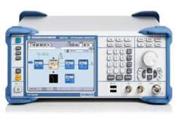
The R&S SMBV100A is a vector signal generator built around a future-ready hardware concept, with an RF section delivering high output level up to 6 GHz and ongoing software upgradeability. It combines a flexible RF path with optional internal baseband signal generation, allowing the same instrument to act as a general-purpose stimulus source or an application-specific signal source.
A vector signal generator produces modulated RF test signals that stimulate a device under test so its response can be measured. The SMBV100A is prepared for aerospace and defense applications, with the ability to generate unmodulated as well as complex modulated pulses and to couple multiple instruments for phase-coherent RF generation. It is also optimized for high production throughput through multisegment waveform mode for fast switchover between test sequences and high level repeatability for stable test conditions.
ValueTronics stocks and holds its own inventory in a 20,000 sq ft secure warehouse at 1675 Cambridge Drive in Elgin, Illinois. Every used unit we sell is inspected and functionally verified in-house before it ships, while new units ship factory-sealed exactly as received from the manufacturer. That combination of on-hand inventory and in-house verification lets a buyer source an SMBV100A configured for their application and know its condition before it arrives.
Rohde & Schwarz is an independent electronics company headquartered in Munich, Germany, founded more than 80 years ago. It has operated continuously under the Rohde & Schwarz name without a major corporate rebrand or acquisition-driven name change.
| Specification | Value |
|---|---|
| Frequency | |
| Range (R&S SMBV-B103), CW mode | 9 kHz to 3.2 GHz |
| Range (R&S SMBV-B103), I/Q mode | 1 MHz to 3.2 GHz |
| Range (R&S SMBV-B106), CW mode | 9 kHz to 6 GHz |
| Range (R&S SMBV-B106), I/Q mode | 1 MHz to 6 GHz |
| Resolution of setting | 0.001 Hz |
| Resolution of synthesis (f = 1 GHz) | 0.44 µHz (nom.) |
| Setting time, ALC state on, CW mode | < 1.5 ms |
| Setting time, ALC state on, I/Q mode | < 3 ms |
| Setting time, ALC state Table | < 2.5 ms |
| Setting time, ALC state S&H | < 3.5 ms |
| Setting time, after trigger pulse in List mode | < 1.0 ms |
| Resolution of phase offset setting | 0.1° |
| Frequency Sweep | |
| Operating mode | digital sweep in discrete steps |
| Step size, linear | full frequency range, minimum 0.001 Hz |
| Step size, logarithmic | 0.01 % to 100 % |
| Dwell time range | 10 ms to 100 s |
| Dwell time resolution | 0.1 ms |
| Reference Frequency | |
| Frequency error, at time of calibration in production | < 1 × 10⁻⁷ |
| Frequency error, with R&S SMBV-B1, R&S SMBV-B1H option | < 1 × 10⁻⁸ |
| Aging (after 10 days of uninterrupted operation) | < 1 × 10⁻⁶/year |
| Aging, with R&S SMBV-B1 option | < 1 × 10⁻⁹/day, < 1 × 10⁻⁷/year |
| Aging, with R&S SMBV-B1H option | < 5 × 10⁻¹⁰/day, < 3 × 10⁻⁸/year |
| Output of internal reference, output frequency | 10 MHz or external input frequency |
| Output level | +7 dBm to +13 dBm, +10 dBm (typ.) |
| Input for external reference, input frequency | 5 MHz, 10 MHz |
| Input level range | 0 dBm to +16 dBm |
| Level | |
| Setting range, 1 MHz ≤ f ≤ 6 GHz | –145 dBm to +30 dBm |
| Setting range, 300 kHz ≤ f < 1 MHz | –145 dBm to +18 dBm |
| Setting range, 100 kHz ≤ f < 300 kHz | –145 dBm to +13 dBm |
| Setting range, 9 kHz ≤ f < 100 kHz | –145 dBm to +8 dBm |
| Specified level range, CW mode, 1 MHz ≤ f ≤ 6 GHz | –120 dBm to +18 dBm (PEP) |
| Specified level range, I/Q mode, 1 MHz ≤ f ≤ 6 GHz | –120 dBm to +18 dBm (PEP) |
| Resolution of setting | 0.01 dB |
| Level error, 200 kHz ≤ f ≤ 3 GHz | < 0.5 dB |
| Level error, f > 3 GHz | < 0.9 dB |
| Output impedance VSWR in 50 Ω system (f > 200 kHz) | < 1.8 |
| Reverse power, 1 MHz ≤ f ≤ 1 GHz | 50 W |
| Reverse power, 1 GHz < f ≤ 2 GHz | 25 W |
| Reverse power, 2 GHz < f ≤ 6 GHz | 10 W |
| Maximum permissible DC voltage | 50 V |
| Level Sweep | |
| Sweep range, interruption-free | –20 dB to +20 dB |
| Step size setting resolution | 0.01 dB |
| Dwell time setting range | 10 ms to 100 s |
| Spectral Purity | |
| Harmonics (CW, I/Q mode, f > 1 MHz, level ≤ 8 dBm) | < –30 dBc |
| Nonharmonics, f ≤ 1500 MHz | < –70 dBc, < –84 dBc (typ.) |
| Nonharmonics, 1500 MHz < f ≤ 3 GHz | < –64 dBc, < –78 dBc (typ.) |
| Nonharmonics, f > 3 GHz | < –58 dBc, < –72 dBc (typ.) |
| Wideband noise (level > 5 dBm, offset > 10 MHz, 1 Hz BW, CW) | < –142 dBc |
| SSB phase noise, f = 100 MHz, CW mode (20 kHz offset) | < –141 dBc, –148 dBc (typ.) |
| SSB phase noise, f = 1 GHz (CW and I/Q mode) | < –122 dBc, –128 dBc (typ.) |
| SSB phase noise, f = 2 GHz | < –116 dBc, –122 dBc (typ.) |
| SSB phase noise, f = 3 GHz | < –112 dBc, –118 dBc (typ.) |
| SSB phase noise, f = 6 GHz | < –106 dBc, –112 dBc (typ.) |
| Residual FM (0.03 kHz to 23 kHz, f = 1 GHz, CW) | < 10 Hz, 1.3 Hz (typ.) |
| Residual AM (0.03 kHz to 20 kHz, level = 8 dBm) | < 0.02 % |
| List Mode | |
| Max. number of stored settings | 2000 |
| Dwell time setting range | 1 ms to 100 s |
| Amplitude Modulation | |
| Modulation source | internal, external, internal + external |
| AM depth setting range | 0 % to 100 % |
| AM depth (m) error, fmod = 1 kHz, m < 80 %, f ≤ 23.4375 MHz | < (1 % of setting + 1 %) |
| AM distortion, fmod = 1 kHz, f ≤ 23.4375 MHz, m = 30 % | < 0.25 % |
| Frequency Modulation | |
| Maximum deviation, f ≤ 23.4375 MHz | 1 MHz |
| Maximum deviation, FM mode normal, f > 23.4375 MHz | N × 2 MHz |
| FM deviation error, internal | < (2 % of setting + 20 Hz) |
| FM distortion (fmod = 2 kHz, deviation = N × 1 MHz) | < 0.2 % |
| Phase Modulation | |
| Maximum deviation, f ≤ 23.4375 MHz | 2 rad |
| Maximum deviation, φM mode high deviation, f > 23.4375 MHz | N × 40 rad |
| φM distortion (fmod = 10 kHz, half of max. deviation) | < 0.2 % |
| Pulse Modulation (R&S SMBV-K22 option) | |
| On/off ratio | > 80 dB |
| Rise/fall time (10 % to 90 %, f > 23.4375 MHz) | < 20 ns, < 5 ns (typ.) |
| Pulse repetition frequency | 0 Hz to 25 MHz |
| Internal Modulation Generator (LF) | |
| Waveform | sine wave, square wave |
| Frequency range, sine wave | 0.1 Hz to 1 MHz |
| Frequency range, square wave | 0.1 Hz to 20 kHz |
| Output voltage range (Vp at LF connector, open circuit) | 1 mV to 3 V |
| Pulse Generator (R&S SMBV-K23 option) | |
| Pulse mode | single pulse, double pulse |
| Pulse period setting range | 40 ns to 85 s |
| Pulse width setting range | 10 ns to 1 s |
| I/Q Modulator | |
| Operating modes | external I/Q, internal I/Q |
| Carrier leakage (referenced to full-scale input) | < –50 dBc, < –65 dBc (typ.) |
Important: The base unit must be ordered with an RF frequency option (R&S SMBV-B103 for 9 kHz to 3.2 GHz or R&S SMBV-B106 for 9 kHz to 6 GHz).
Important: Only one of the reference oscillator options (R&S SMBV-B1 or R&S SMBV-B1H) can be installed.
Important: The R&S SMBV-B10/-B10F baseband generator options require the R&S SMBV-B92 option (hard disk).
Important: Maximum permissible reverse RF power into the RF output (for f ≥ 1 MHz): 50 W for 1 MHz ≤ f ≤ 1 GHz, 25 W for 1 GHz < f ≤ 2 GHz, and 10 W for 2 GHz < f ≤ 6 GHz; maximum permissible DC voltage 50 V.
Important: R&S SMBV-B10F may be subject to export restrictions and therefore not available in all countries and to all customers.
Important: R&S WinIQSIM2 options require an external PC.
Recommended pairing: the R&S NRP-Z92 power sensor (9 kHz to 6 GHz), listed among the recommended extras, supports external power measurements and level adjustment of the instrument.
This pre-owned unit is inspected and functionally verified in-house before it ships and is backed by our pre-owned warranty. To confirm its exact condition, firmware revision, installed options, or included accessories for your application before ordering, contact our Test Architects.
ValueTronics supplies both new and used test and measurement equipment. New units ship factory-sealed, exactly as received from the manufacturer; every used unit is inspected and functionally verified in-house at our 20,000 sq ft secure facility in Elgin, Illinois before it ships. Our Test Architects can help you select the condition, calibration, and configuration that fit your application.
Please review the Manufacturer's Data Sheet to verify published specifications. Feedback on this webpage is always welcome — please reach out to your Test Architect at any time for questions or concerns. Thank you, we truly appreciate you being our customer.
Model No
Rohde
Condition
Pre-Owned
Manufacturer
Rohde & Schwarz
Rf_gen_freq
9 kHz to 6 GHz
B103
9 kHz to 3.2 GHz
B106
9 KHZ TO 6 GHZ
K256
PLAYBACK OF XM RADIO WAVEFORMS
K352
PLAYBACK OF HD RADIO™ WAVEFORMS
K511
MEMORY EXTENSION FOR ARB TO 256 MSAMPLE
K512
MEMORY EXTENSION FOR ARB TO 1 GSAMPLE
SM-B5
FM/?M Modulator
SMIQB11
Data Generator
SMIQB20
Modulation Coder

30+ Years in Business
Secure Payments
Sell Test Equipments
Knowledgeable Staff
On-site Lab
30+ Years in Business
Secure Payments
Sell Test Equipments
Knowledgeable Staff
On-site Lab
Request A Quote
 Chat Live
 Contact Us
 sales@valuetronics.com