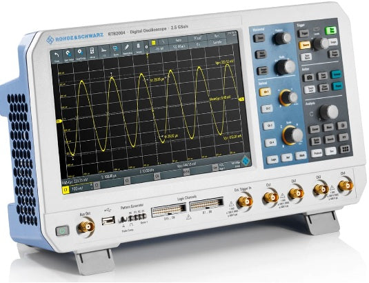
In summary, the Rohde & Schwarz RTB2K-72M is a two-channel 70 MHz MSO configuration with 16 digital channels within the R&S RTB 2 Series family. It pairs a 10-bit ADC with a 10.1" capacitive touch interface and delivers up to 2.5 Gsample/s interleaved sampling, 10 Msample standard memory per channel, and 1 mV/div input sensitivity across the full analog bandwidth — a combination aimed at engineers who want precise vertical resolution without sacrificing the responsive touchscreen workflow of a modern bench scope.
The RTB2K-72M is used for embedded firmware, automotive, and IoT engineers who need to time-correlate analog signals with digital bus traffic on the same screen. Typical tasks include power-rail integrity checks, switching-loss analysis, serial-bus debug (I²C, SPI, UART, CAN, LIN with the corresponding decode options), frequency-response measurements via the Bode-plot option, and mask-based production go/no-go testing.
A 10-bit converter resolves 1024 vertical levels — four times the granularity of a conventional 8-bit scope. With high-resolution decimation engaged, effective resolution rises to 16 bit, which is particularly useful for low-amplitude signals riding on a DC offset (ripple on a regulator output, sensor mV-level swings, or noise-floor characterization on a power rail).
The RTB2K-72M provides 70 MHz of analog bandwidth (–3 dB), 2 analog input channels at 1 MΩ ± 2 % (9 pF ± 2 pF) input impedance, an input sensitivity range of 1 mV/div to 5 V/div, and a maximum input voltage of 300 V (RMS) (400 V peak), derating at 20 dB/decade to 5 V (RMS) above 250 kHz. Timebase ranges from 1 ns/div to 500 s/div with ±2.5 ppm accuracy after delivery/calibration at +23 °C. Trigger types include edge, width, video, pattern, runt, rise/fall time, serial bus, timeout, and line. The waveform acquisition rate reaches up to 50,000 waveforms/s in dot display mode.
The base unit is engineered against IEC 61010-1, EN 61010-1, CAN/CSA-C22.2 No. 61010-1-04, and UL 61010-1 safety standards, and certified to VDE and CCSAUS. EMC compliance follows CISPR 11 / EN 55011 group 1 class A and IEC/EN 61326-1 table 2 industrial-environment immunity requirements. The recommended calibration interval is 1 year. Rohde & Schwarz is a privately held, family-owned company headquartered in Munich, Germany, with an installed base trusted in defense, aerospace, telecom, broadcast, and demanding RF-adjacent labs across Europe and globally.
| Passive probe | One 300 MHz, 10:1, 10 MΩ, 400 V (RMS) passive probe per analog channel (R&S RT-ZP03S) |
|---|---|
| Logic probes | Two R&S RT-ZL03 active 8-channel logic probes (RTB2-B1 mixed-signal option, 16 digital channels total) |
| Power cord | Region-appropriate AC power cord |
| Documentation | Getting started manual and safety instructions |
The RTB2K-72M is built around the same 70 MHz, 10-bit acquisition platform that defines the R&S RTB 2 Series. Bandwidth is set in the factory or upgraded later via keycode, and the same platform supports an optional 16-channel logic probe set (RTB2-B1) and an application-software bundle (I²C/SPI, UART/RS-232/422/485, CAN/LIN, and frequency-response analysis) without changing the underlying hardware. The result is a single chassis that scales from 70 MHz 2-channel DSO work up to a mixed-signal embedded-debug bench with serial decode and Bode-plot analysis.
| Parameter | Value |
|---|---|
| Input channels | 2 analog channels |
| Input impedance | 1 MΩ ± 2 % with 9 pF ± 2 pF (meas.) |
| Analog bandwidth (–3 dB) | > 70 MHz |
| Lower frequency limit (–3 dB, AC coupling) | < 2 Hz (meas.) |
| Bandwidth limit (selectable) | 20 MHz (max. –1.8 dB, min. –3.5 dB) |
| Rise time (10 % to 90 %, calculated) | < 5 ns |
| Vertical resolution | 10 bit; up to 16 bit with high-resolution decimation |
| Input sensitivity | 1 mV/div to 5 V/div |
| DC gain accuracy (sensitivity > 5 mV/div) | ±1.5 % of full scale |
| DC gain accuracy (sensitivity ≤ 5 mV/div) | ±2 % of full scale |
| Offset accuracy | ±(0.5 % × |offset| + 0.1 div × input sensitivity + 1 mV) |
| Input coupling | DC, AC (> 7 Hz) |
| Maximum input voltage | 300 V (RMS), max. 400 V (Vp); derates at 20 dB/decade to 5 V (RMS) above 250 kHz |
| Position range | ±5 div (depends on offset) |
| Channel-to-channel isolation (input freq < analog BW) | > 50 dB |
| Invert signal | Yes |
| Parameter | Value |
|---|---|
| Timebase range | 1 ns/div to 500 s/div |
| Channel deskew | ±500 ns |
| Modes | Normal, roll (≥ 50 ms/div) |
| Timebase accuracy (after delivery / calibration, +23 °C) | ±2.5 ppm |
| Timebase accuracy (during calibration interval) | ±3.5 ppm |
| Max. realtime sampling rate (normal) | 1.25 Gsample/s |
| Max. realtime sampling rate (interleaved) | 2.5 Gsample/s |
| Memory depth (normal) | 10 Msample per channel |
| Memory depth (interleaved) | 20 Msample per channel |
| Acquisition modes | Sample, peak detect (800 ps), high resolution, envelope, average, envelope + peak detect |
| Number of averaged waveforms | 2 to 100,000 |
| Waveform acquisition rate | up to 50,000 waveforms/s (dot display, single channel, auto record length) |
| Parameter | Value |
|---|---|
| Trigger modes | Auto, normal, single; n single with RTB-K15 option |
| Trigger types | Edge, width, video, pattern, runt, rise time, fall time, serial bus, timeout, line |
| Hold-off range | Inactive, or 50 ns to 10 s |
| Pulse width min / max | 6.4 ns / 13.5 s |
| Video trigger standards | PAL, NTSC, SECAM, PAL-M, SDTV 576i |
| External trigger input impedance | 1 MΩ ± 2 % with 9 pF ± 2 pF (meas.) |
| Trigger level (analog channels) | ±5 div from center of screen |
| Trigger output (AUX OUT) | 0 to 4.8 V at high Z; 0 to 2.4 V into 50 Ω; high-active pulse per acquisition trigger |
| Serial bus protocols (with option) | I²C / SPI (RTB-K1), UART / RS-232 / RS-422 / RS-485 (RTB-K2), CAN / LIN (RTB-K3) |
| Parameter | Value |
|---|---|
| Automatic measurements | burst width; count positive / negative pulses; count rising / falling edges; mean; RMS cycle; RMS; mean cycle; peak-peak; peak+; peak–; frequency; period; amplitude; top / base level; positive / negative overshoot; pulse width +/–; duty cycle +/–; rise / fall time; delay; phase; crest factor; slew rate +/–; σ std deviation; σ std deviation cycle; delay to trigger |
| Number of active measurements | 8 |
| Cursors | Vertical, horizontal, V-marker; x/y tracking; coupling of cursors; two sources |
| Math waveforms | Up to 5 (add, subtract, multiply, divide, square, sqrt, abs, reciprocal, inverse, log10, ln, derivation, integration, low/high pass, track period / frequency / pulse width / duty cycle) |
| FFT | Start / stop / center / span freq, vertical scale & position, RBW, gate; windows: Hanning, Hamming, Blackman, rectangular, flat top; min/max hold, average 2–1024; dBm, dBV, dBµV, V (RMS) |
| Digital voltmeter | DC, AC+DC (RMS), AC (RMS); up to 4 measurements; up to 3 digits; 1 MHz bandwidth |
| Frequency counter | Frequency, period; 6-digit resolution; 0.05 Hz to scope bandwidth |
| Mask testing | Acquired waveform with user tolerance; pass/fail statistics; actions: sound, acquisition stop, screenshot, save waveform, pulse out |
| Parameter | Value |
|---|---|
| Logic input channels | 16 channels (D15 to D0), two R&S RT-ZL03 logic probes (8 channels each) |
| Input impedance | 100 kΩ ± 2 % || ~4 pF (meas.) at probe tip |
| Max. input frequency | 300 MHz (meas.) at normal hysteresis & minimum input swing |
| Max. input voltage | ±40 V (Vp); 32 V (RMS), derates to 7 V (RMS) at 20 dB/decade above 25 MHz |
| Minimum input voltage swing | 300 mV (Vpp) small / 800 mV medium / 1500 mV large hysteresis |
| Threshold groups | D15–D8 and D7–D0 independently |
| Threshold range | –2 V to 8 V in 10 mV steps; predefined: CMOS 5.0 V, CMOS 3.3 V, CMOS 2.5 V, TTL, ECL |
| Threshold accuracy | ±(100 mV + 3 % of threshold setting) (meas.) |
| Sample rate | 1.25 Gsample/s per channel |
| Memory depth | 10 Msample/ch (two probes); 20 Msample/ch (single probe, interleaved) |
| Channel-to-channel skew | Max. 800 ps (meas.) |
| Parameter | Value |
|---|---|
| Resolution / sample rate | 14 bit / 250 Msample/s |
| Amplitude (high Z / 50 Ω) | 20 mV – 5 V (Vpp) high Z; 10 mV – 2.5 V (Vpp) 50 Ω; accuracy 3 % (≤ 100 kHz) |
| DC offset (high Z / 50 Ω) | ±2.5 V / ±1.25 V; accuracy 3 % or ±5 mV whichever greater |
| Sine | 0.1 Hz – 25 MHz; SFDR > 40 dBc; THD > 40 dBc (both meas.) |
| Rectangle / Pulse | 0.1 Hz – 10 MHz; pulse duty cycle 1 % – 99 %, adjustable edge time |
| Ramp / triangle / sinc / exponential | 0.1 Hz – 1 MHz |
| Arbitrary | 0.1 Hz – 10 MHz; 16 kpoints memory |
| Noise | Bandwidth max. 25 MHz; level 0 % – 100 % of amplitude |
| Modulation | AM, FM, ASK, FSK; modulating freq 0.1 Hz – 1 MHz |
| Sweep | 1 Hz – 25 MHz start/stop; 1 ms – 10 s sweep time; linear / log / triangle |
| Burst | 1 – 1024 cycles; 28 ns – 17 s idle time; 0° – 360° start phase |
| 4-bit pattern generator | Probe adjust (1 kHz / 1 MHz square ≈ 2.5 Vpp); bus signal sources for SPI, I²C, UART, CAN, LIN at 9600 bps – 1 Mbps; 4-bit counter 1 mHz – 25 MHz; programmable pattern 2048-bit memory |
| Parameter | Value |
|---|---|
| Display | 10.1" WXGA capacitive touch, 1280 × 800 |
| Diagram types | Yt, XY, zoom, FFT (manually changeable vertical window size) |
| Persistence | 50 ms to 12.8 s, infinite |
| Reference signals | Up to 4 |
| USB host (front) | 1 × Type A, USB 2.0, FAT32 USB drives only |
| USB device (rear) | 1 × Type B, USB 2.0 |
| Ethernet | 1 port, 1 Gbit |
| AUX OUT (BNC) | Trigger out, 10 MHz reference (±3.5 ppm meas.), mask violation pulse, waveform-generator output |
| Probe compensation output | Rectangle Vlow 0 V, Vhigh 2.5 V (meas.); 1 kHz during probe adjust or manual |
| Operating temperature | 0 °C to +50 °C |
| Storage temperature | –40 °C to +70 °C |
| Altitude (operating / non-op) | 3000 m / 4600 m |
| Power supply | 100 V – 240 V at 50 Hz – 400 Hz, 0.95 A – 0.5 A; max. 60 W |
| Power consumption in stand-by | 0.5 W (meas.) |
| Dimensions (W × H × D) | 390 mm × 220 mm × 152 mm (15.4 in × 8.66 in × 5.98 in) |
| Weight (nom.) | 2.5 kg (5.5 lb) |
| EMC | CISPR 11 / EN 55011 group 1 class A; IEC/EN 61326-1 table 2 industrial-immunity |
| Safety | IEC 61010-1, EN 61010-1, CAN/CSA-C22.2 No. 61010-1-04, UL 61010-1 |
| Certifications | VDE, CCSAUS |
| Calibration interval | 1 year |
| Warranty (base unit) | 3 years (base unit); 1 year all other items |
| Option | Description |
|---|---|
| RTB-B221 / B222 / B223 | Bandwidth upgrade for RTB22 → 100 / 200 / 300 MHz |
| RTB-B241 / B242 / B243 | Bandwidth upgrade for RTB24 → 100 / 200 / 300 MHz |
| RTB2-B1 | Mixed-signal option: 16 logic channels with two RT-ZL03 logic probes (300 MHz) |
| RTB-K1 | I²C / SPI triggering and decoding (up to 10 Mbps I²C; 25 Mbps SPI) |
| RTB-K2 | UART / RS-232 / RS-422 / RS-485 triggering and decoding (up to 3 Mbps) |
| RTB-K3 | CAN / LIN triggering and decoding (CAN to 2 Mbps; LIN to 2.5 Mbps) |
| RTB-K36 | Frequency response analysis (Bode plot), 10 Hz – 25 MHz, > 70 dB dynamic range (typ.) |
| RTB2-PK1 | Application bundle: RTB-K1 + RTB-K2 + RTB-K3 + RTB-K36 |
This webpage was written by a human with an A.I. "Intern", which may contain errors. Please review the Manufacturers Data Sheet to verify published specifications. Feedback on this webpage is always welcome, please reach out to your Test Architect at any time for questions or concerns. Thank you, we truly appreciate you being our customer.
Model No
RTB2K-72M
Condition
New
Manufacturer
Rohde & Schwarz
Channels
2+16
Frequency
70 MHz
Record length
20 MPts
Sampling rate
2.5 GS/s

30+ Years in Business
Secure Payments
Sell Test Equipments
Knowledgeable Staff
On-site Lab
30+ Years in Business
Secure Payments
Sell Test Equipments
Knowledgeable Staff
On-site Lab
Request A Quote
 Chat Live
 Contact Us
 sales@valuetronics.com