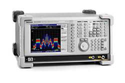
The Tektronix RSA3408B is a DC to 8 GHz Real-Time Spectrum Analyzer (RTSA) that combines the functionality of a high-performance vector signal analyzer, a spectrum analyzer, and a real-time spectrum analyzer in a single package. Its revolutionary DPX spectrum display offers an intuitive live color view of signal transients changing over time in the frequency domain, giving immediate confidence in the stability of a design or instantly displaying a fault when it occurs. Once a problem is discovered with DPX, the instrument can be set to trigger on the event in the frequency domain, capture a continuous time record of changing RF events, and perform time-correlated analysis across all domains.
The RSA3408B is applied to RF debug of components, modules, or systems; finding interference and unknown signals in spectrum monitoring and management; analyzing the time-variant behavior of standards-based and other radio systems; field tactical radio transceiver measurements; and characterizing radar and pulsed RF signals. It also provides powerful vector signal analyzer functionality and signal source analysis capability, along with comprehensive analog demodulation and audio distortion measurement for tactical radio and sonar systems.
ValueTronics stocks and holds its own inventory in a 20,000 sq ft secure warehouse at 1675 Cambridge Drive in Elgin, Illinois, which lets us match the right instrument to an application and ship it promptly. Every pre-owned unit is inspected and functionally verified in-house against the original manufacturer's specifications before it leaves our facility, while new units ship factory-sealed exactly as received from the manufacturer.
| Specification | Value |
|---|---|
| Trigger-related | |
| Trigger Modes | Free run, Triggered (Single or Continuous) |
| Trigger Event Source | RF Input, External Trigger Input |
| Trigger Types | Power Level; Frequency Mask (Opt. 02) |
| Trigger Position | Settable from 0 to 100% of total acquisition length |
| Power Level Trigger – Level Range | 0 dBfs to –40 dBfs from reference level |
| Power Level Trigger – Trigger Bandwidth Range | 100 Hz to 36 MHz (equal to selected span) |
| Trigger Position Display Timing Uncertainty (Power and External Trigger) | ±2 sample points |
| Frequency Mask Trigger (Option 02) | |
| Mask Shape | User-defined |
| Mask Point Horizontal Resolution | 1 bin |
| Level Range | 0 to –60 dBfs at 10 dB/div vertical scale |
| Level Accuracy | Equal to reference level accuracy + frequency response over 0 to –60 dBfs range |
| Span Range (Start Frequency ≥40 MHz) | 100 Hz to 36 MHz |
| Span Range (Start Frequency < 40 MHz) | 100 Hz to 40 MHz |
| Minimum Event Duration for 100% Probability of Trigger | 20 µs (at maximum acquisition bandwidth) |
| Trigger Position Uncertainty | ±2 Frames (For Span = 36 MHz, uncertainty = ±40 µs) |
| External Trigger | |
| Level Range | –1.5 V to +1.5 V |
| Level Setting Resolution | 0.1 V |
| Trigger Position Timing Uncertainty | ±2 samples |
| Input Impedance | > 2K Ω (nominal) |
| Trigger Output | |
| Voltage | HIGH ≥2.0 V; LOW <0.4 V (Output Current <1 mA) |
| Capture-related | |
| Real-time Acquisition Bandwidth, maximum (Start Frequency ≥40 MHz, RF) | 36 MHz |
| Real-time Acquisition Bandwidth, maximum (Start Frequency <40 MHz, Baseband) | 40 MHz |
| Real-time Acquisition Bandwidth, maximum (IQ Inputs, Option 03) | 40 MHz |
| A/D Converter | 102.4 MS/s, 14 bit |
| Acquisition Memory Size | 64 MB (16.4 MSamples) Standard, 256 MB (65.6 MSamples) Opt. 02 |
| Minimum Acquisition Length | 1024 Samples |
| Acquisition Length Setting Resolution | 1024 Samples |
| Spectrum Mode Display Traces, Detectors and Functions | |
| Traces | Two traces |
| Detector | Max, Min, Max-Min |
| Trace Functions | Normal, Average, Max Hold, Min Hold |
| Spectrum Trace Length | 801 points (Auto mode) |
| Frequency (RF Performance) | |
| Frequency Range | DC to 8 GHz |
| Initial Center Frequency Setting Accuracy | within 10–7 after 10 minute warm-up |
| Center Frequency Setting Resolution | 0.1 Hz |
| Span Accuracy | ±0.3% (Auto mode) |
| Reference Frequency – Aging per Day | 1 x 10⁻⁹ (after 30 days of operation) |
| Reference Frequency – Aging per Year | 1 x 10⁻⁷ (after 30 days of operation) |
| Reference Frequency – Temperature Drift | 1 x 10⁻⁷ (10 °C to 40 °C) |
| Total Frequency Error | 2 x 10⁻⁷ (within one year after calibration) |
| Reference Output Level | > 0 dBm |
| External Reference Input Frequency | 10 MHz |
| External Reference Input Level Range | –10 dBm to +6 dBm, Spurious level must be < –80 dBc within 100 kHz offset |
| Resolution Bandwidth (Spectrum Analysis Mode) | |
| Resolution Bandwidth Range | 1 Hz to 10 MHz (auto-coupled or user-selected) |
| Resolution Bandwidth Shape | Approximately Gaussian, shape factor <5:1 (60:3 dB) typical; Rectangular, Nyquist and Root Nyquist shapes may also be selected |
| Resolution Bandwidth Accuracy | Within 6% (referenced to –3 dB BW); ±0.1% (referenced to Noise BW) |
| DPX Digital Phosphor Spectrum Processing | |
| Spectrum Processing Rate | 48,000/s, span-independent |
| Number of Traces | 2 |
| Trace Types | Color-graded bit map, +Peak, Max Hold, –Peak, Min-Hold, Average |
| Minimum Signal Duration for 100% Probability of Intercept | 31 µs |
| Span Range | 100 Hz to 36 MHz |
| Resolution BW Accuracy | 7% |
| Stability | |
| Residual FM | < 2 Hz p-p, typical |
| Phase Noise Sidebands, dBc/Hz (CF = 1 GHz, Spec) | |
| 1 kHz offset | –105 |
| 10 kHz offset | –110 |
| 100 kHz offset | –112 |
| 1 MHz offset | –132 |
| 5 MHz offset | –138 |
| 10 MHz offset | –138 |
| Amplitude (excluding mismatch error) | |
| Measurement Range | Displayed Average Noise Level to Maximum Safe Input |
| Input Attenuator Range – RF/Baseband input | 0 dB to 55 dB, 5 dB step |
| Input Attenuator Range – IQ Input (Opt 03) | 0 dB to 35 dB, 5 dB step |
| Maximum Safe Input Level – Average Continuous (RF Band, RF ATT ≥10 dB) | +30 dBm |
| MAX DC Voltage | RF Band ±0.2 V, Baseband ±5 V, IQ input (Opt. 03) ±5 V |
| Maximum Measurable Input Level – Average Continuous (RF ATT: Auto) | +30 dBm |
| Log Display Scale | 10 µdB/div to 10 dB/div |
| Display Divisions | 10 divisions |
| Display Units | dBm, dBµV, Volts, Watts, Hz, Degrees |
| Marker Readout Resolution, dB units | 0.01 dB |
| Marker Readout Resolution, Volts units | 0.001 µV |
| Reference Level Setting Range – RF | –50 dBm to +30 dBm, 1 dB step |
| Reference Level Setting Range – Baseband | –30 dBm to +20 dBm, 5 dB step |
| Reference Level Setting Range – IQ Inputs (Option 03) | –10 dBm to +20 dBm, 5 dB step |
| Level Linearity over Display Range | ±0.2 dB spec; ±0.12 dB typical |
| Frequency Response (20 ºC to 30 ºC, Att. ≥10 dB) | |
| 100 kHz to 40 MHz | ±0.5 dB spec; ±0.3 dB typical |
| > 40 MHz to 3.5 GHz | ±1.2 dB spec; ±0.5 dB typical |
| > 3.5 GHz to 6.5 GHz | ±1.7 dB spec; ±1.0 dB typical |
| > 6.5 GHz to 8 GHz | ±1.7 dB spec; ±1.0 dB typical |
| Amplitude Accuracy (–20 dBm signal, 0 dB ATT, 20 ºC to 30 ºC) | |
| Absolute Amplitude Accuracy at Calibration Point – RF (100 MHz) | ±0.5 dB |
| Absolute Amplitude Accuracy at Calibration Point – Baseband (25 MHz) | ±0.3 dB |
| Input Attenuator Setting Uncertainty | ±0.2 dB |
Important: Maximum safe input level: +30 dBm average continuous (RF band, RF attenuation ≥10 dB). Maximum DC voltage: ±0.2 V (RF band), ±5 V (Baseband and IQ input, Opt. 03).
Important: Data from Option 05 (Digital IQ Output) requires application of correction factors to IQ data to achieve similar RF performance to the RSA3408B.
Important: Frequency Mask Trigger (Option 02): events lasting less than the minimum event duration specification (20 µs at maximum acquisition bandwidth) will result in degraded Frequency Mask Trigger level accuracy.
Recommended pairing: use the RTPA2A adapter to connect Tektronix TekConnect active and passive probes for in-circuit troubleshooting, with probe calibration factors transferred via USB for calibrated measurements.
This pre-owned unit is inspected and functionally verified in-house before it ships and is backed by our pre-owned warranty. To confirm its exact condition, firmware revision, installed options, or included accessories for your application before ordering, contact our Test Architects.
ValueTronics supplies both new and used test and measurement equipment. New units ship factory-sealed, exactly as received from the manufacturer; every used unit is inspected and functionally verified in-house at our 20,000 sq ft secure facility in Elgin, Illinois before it ships. Our Test Architects can help you select the condition, calibration, and configuration that fit your application.
Please review the Manufacturer's Data Sheet to verify published specifications. Feedback on this webpage is always welcome — please reach out to your Test Architect at any time for questions or concerns. Thank you, we truly appreciate you being our customer.
Model No
Tektronix
Condition
Pre-Owned
Manufacturer
Tektronix
Spec_ana_freq
DC to 8 GHz

30+ Years in Business
Secure Payments
Sell Test Equipments
Knowledgeable Staff
On-site Lab
30+ Years in Business
Secure Payments
Sell Test Equipments
Knowledgeable Staff
On-site Lab
Request A Quote
 Chat Live
 Contact Us
 sales@valuetronics.com