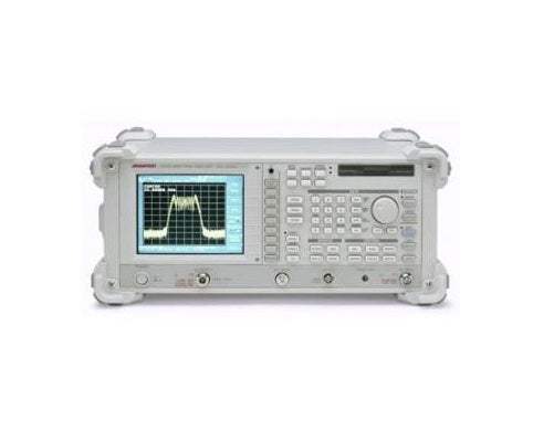
The R3754 Series is an Advantest network analyzer with its measurement frequency range set to 10 kHz to 150 MHz. It is built for adjustment and test in the production and inspection processes of crystal, ceramic, LC, and sensor parts, pairing enhanced functional performance with a low price point. Two display types are offered: the R3754A with a 5-inch monochrome LCD and the R3754B with a 6.5-inch color TFT LCD.
Within the crystal device manufacturing process, the series supports pre-process measurements such as blank selection and frequency adjustment, along with equivalent circuit constant analysis. In the ceramic device manufacturing process it handles frequency selection of the ceramic base, direct filter analysis at resonant and anti-resonant points, and filter/resonator spurious measurement. Advantest recommends the R3754A for the pre-process and the R3754B for shipment inspection and receiving inspection.
ValueTronics stocks and holds its own inventory in a 20,000 sq ft secure warehouse at 1675 Cambridge Drive in Elgin, Illinois. Every pre-owned unit is inspected and functionally verified in-house against the original manufacturer specifications before it ships, while new units leave factory-sealed exactly as received. That combination lets buyers source this instrument with confidence in its condition and availability.
Advantest Corporation traces its roots to Takeda Riken, the test-equipment maker that adopted the Advantest name in 1985. The instrument brand has carried that name consistently since.
The R3754 Series comprises two main-unit models that share the same network-analyzer architecture, frequency range, and basic performance, differing in their display unit. The R3754A uses a 5-inch STN monochrome LCD and the R3754B uses a 6.5-inch color TFT LCD, both at 640 x 640 dots.
Advantest positions the two display variants by process stage: the R3754A is recommended for the pre-process, while the color R3754B is recommended for shipment inspection and receiving inspection where on-screen color coding aids clarity. Both models accept the same input-channel and function options.
Each pre-owned model below is its own dedicated product page with condition-matched pricing. Select the model and channel configuration that fits your application, and the linked page reflects current availability and pricing for that exact unit.
The primary difference between the two models is the display: the R3754A ships with a 5-inch STN monochrome LCD (with contrast control and backlight on/off), and the R3754B ships with a 6.5-inch color TFT LCD supporting 256-color user editing. Core measurement performance such as the 127 dB dynamic range, 0.05 ms/point sweep, and 10 kHz to 150 MHz range is common to both.
Input channel count is set by option rather than by model: a single channel is standard, Option 10 adds a second channel, and Option 11 provides three channels for 2-device simultaneous measurement. Function options including RLA drive level measurement (Option 71), TDR (Option 70), and 3-terminal resonator measurement (Option 72) apply across the family. See the comparison table for the per-model and per-option breakdown.
| Model | Display | Frequency Range | Max Sweep Speed |
|---|---|---|---|
| R3754B | 6.5-inch Color TFT LCD | 10 kHz to 150 MHz | 0.05 ms/point (RBW 15 kHz) |
| R3754A | 5-inch STN Monochrome LCD | 10 kHz to 150 MHz | 0.05 ms/point (RBW 15 kHz) |
Additional differences in specifications beyond the few shown above are not listed here — see each model's full specifications below.
| Specification | Value |
|---|---|
| Measurement Function | |
| Measurement channel | 2 channels (4-trace display) |
| Measurement parameter | R; A/R, R, A (Option 10); A/R, B/R, A/B, R, A, B (Option 11) |
| Measurement format (AC/DC display) | Logarithmic/linear amplitude, phase, group delay, real and imaginary portions of complex number parameters; Z, R, X (impedance conversion measurement); Y, G, B (admittance conversion measurement); Phase extension display |
| Smith chart | Logarithmic/linear amplitude and phase for marker reading, real and imaginary portions, R+jX, G+jB |
| Polar coordinates display | Logarithmic/linear amplitude and phase for marker reading, real and imaginary portions |
| Signal Source Characteristics — Frequency (23 ± 5 °C) | |
| Range | 10 kHz to 150 MHz |
| Resolution | 0.1 Hz |
| Accuracy | ±5 ppm (Typ.); ±1 ppm (Option 20) (1 MHz or more, when 0 to +50 °C, after 30 minutes warm-up) |
| Stability | ±2 x 10⁻⁸/day (Option 20) (after 48 hours warm-up) |
| Signal Source Characteristics — Output | |
| Output | +21 dBm to -43 dBm |
| Resolution | 0.1 dB |
| Accuracy | ±0.5 dB (0 dBm, 10 MHz) |
| Linearity (50 MHz) | +21 dBm to -35 dBm: ±0.5 dB; -35 dBm to -43 dBm: ±1.5 dB |
| Flatness (at 0 dBm output) | 10 kHz to 300 kHz: ±2.0 dB; 300 kHz to 150 MHz: ±1.5 dB |
| Impedance (output port 1) | Nominal 50 Ω, Return loss 13 dB or more (at 0 dBm output, Typ.) |
| Signal Source Characteristics — Signal Purity | |
| Harmonic wave distortion | ≤-15 dBc |
| Non-harmonic wave spurious | ≤-20 dBc or -60 dBm, whichever is larger |
| Phase noise | ≤-95 dBc/Hz (10 kHz offset) |
| Sweep Characteristics | |
| Sweep parameter | Frequency, signal level |
| Range | Same as the frequency sweep frequency characteristic; Level sweep +21 dBm to -43 dBm |
| Range setting | Start/Stop or Center/Span |
| Sweep type | Linear/logarithmic frequency sweep, level sweep, sweep of a user-defined segment |
| Sweep time | Max. 0.05 ms/point (RBW 15 kHz) |
| Measurement point | 3, 6, 11, 21, 51, 101, 201, 301, 401, 501, 601, or 1201 points |
| Sweep trigger | Continuous, Single, External |
| Sweep mode | Dual sweep (2-channel sweep in the same frequency range), alternate sweep (2-channel sweep in different frequency ranges) |
| Signal Source Characteristics — Output Form | |
| Output | Single; Single, dual (Option 10, Option 11) |
| Connector | BNC (female), 50 Ω |
| Power splitter (output port 2) | Option 10, Option 11 |
| Insertion loss (Option 10, Option 11) | 6 dB (Typ.) |
| Level tracking (Option 10, Option 11) | <100 MHz: 0.1 dB (Typ.); ≥100 MHz: 0.2 dB (Typ.) |
| Equivalent output SWB (Option 10, Option 11) | <100 MHz: 1.2 (Typ.); ≥100 MHz: 1.4 (Typ.) |
| Reception Section — Input (23 ± 5 °C) | |
| Input channel | 1 ch, 2 ch (Option 10), 3 ch (Option 11) |
| Frequency range | 10 kHz to 150 MHz |
| Impedance | Nominal 50 Ω |
| Return loss | ATT 0 dB: 20 dB or more; ATT 25 dB: 25 dB or more |
| Max. input level | ATT 25 dB / AMP 0 dB: +5 dBm; ATT 0 dB / AMP 0 dB: -20 dBm; ATT 0 dB / AMP 16 dB: -36 dBm |
| Input destruction level | +24 dBm, ±3 VDC |
| Average noise level (RBW 10 kHz) | 200 kHz to 500 kHz: -102 dBm (ATT 0 dB, AMP 16 dB); 500 kHz to 150 MHz: -112 dBm |
| Average noise level (RBW 3 kHz) | 60 kHz to 500 kHz: -107 dBm; 500 kHz to 150 MHz: -117 dBm |
| Average noise level (RBW 1 kHz) | 20 kHz to 500 kHz: -112 dBm; 500 kHz to 150 MHz: -122 dBm |
| Average noise level (RBW 300 Hz) | 10 kHz to 500 kHz: -117 dBm; 500 kHz to 150 MHz: -127 dBm |
| Resolution bandwidth (RBW) | 3 Hz to 15 kHz (1, 1.5, 2, 3, 4, 5, or 7 steps) |
| Input cross-talk | 10 kHz to 500 kHz: 105 dB; 500 kHz to 150 MHz: 120 dB |
| Signal source cross talk | 10 kHz to 500 kHz: 105 dB; 500 kHz to 150 MHz: 120 dB |
| Input connector | BNC (female) 50 Ω |
| Reception Section — Automatic Offset Correction | |
| Normalization function | Compensates the frequency characteristics of the measurement system. |
| Electric length correction | Equivalent electric length or group delay time can be added to the measured phase or group delay time. |
| Range | -3 X 10⁸ m to +3 X 10⁸ m or +10 sec. to -10 sec. |
| Amplitude Characteristics (Absolute) | |
| Measurement range | ATT AUTO / AMP 0 dB: +5 dBm to -115 dBm (RBW 1 kHz); ATT 25 dB / AMP 0 dB: +5 dBm to -90 dBm (100 kHz or more); ATT 0 dB / AMP 0 dB: -20 dBm to -115 dBm; ATT 0 dB / AMP 16 dB: -36 dBm to -122 dBm |
| Display resolution | 0.001 dB/div |
| Accuracy | ±0.5 dB (10 MHz, max. input level) |
| Frequency response (at 0 dBm input) | 10 kHz to 1 MHz: 4 dBp-p; 1 MHz to 150 MHz: 3.5 dBp-p |
| Dynamic accuracy | 0 to -10 dBm: ±0.4 dB (ATT 25 dBm, AMP 0 dB); -10 to -60 dBm: ±0.1 dB (100 kHz or more); -60 to -70 dBm: ±0.2 dB; -70 to -80 dBm: ±0.6 dB |
| Amplitude Characteristics (Relative) — Option 10, Option 11 | |
| Measurement range | ATT AUTO / AMP 0 dB: ±120 dB; ATT 25 dB / AMP 0 dB, ATT 20 dB / AMP 0 dB: ±95 dB (100 kHz or more); ATT 0 dB / AMP 0 dB: ±95 dB; ATT 0 dB / AMP 16 dB: ±86 dB |
| Display resolution | 0.001 dB/div |
| Accuracy | ±0.5 dB (10 MHz, max. input level) |
| Frequency response (at 0 dBm input) | 10 kHz to 1 MHz: 3 dBp-p; 1 MHz to 150 MHz: 2 dBp-p |
| Dynamic accuracy | 0 to -10 dBm: ±0.1 dB (ATT 25 dB, AMP 0 dB); -10 to -60 dBm: ±0.05 dB (100 kHz or more); -60 to -70 dBm: ±0.1 dB; -70 to -80 dBm: ±0.3 dB; -80 to -90 dBm: ±0.9 dB |
| Phase Characteristics (Relative) | |
| Measurement range | ±180° (Continuous display possible for more than ±180° by the display expansion function) |
Important: Input destruction level: +24 dBm, ±3 VDC.
Important: The operating manual is optional and is not included with the main unit (select Option 90 Japanese manual or Option 91 English manual separately).
Important: With a measurement range setting which includes 32.5 MHz, absolute measured phase characteristic values are not guaranteed. They are guaranteed when the unit is used with a measurement range setting between 10 kHz and 32.5 MHz, or between 32.5 MHz and 150 MHz.
Important: The 3-terminal resonator measurement function (Option 72) requires the R1704 and a CAL Kit. The R17041 test fixture and calibration kit are optional and ordered separately.
Important: Additional input channels are optional: the standard unit provides one input channel; 2-channel input is Option 10 and 3-channel input is Option 11.
Important: The 2-channel/4-trace simultaneous (2-device) measurement function requires the 3-channel input model (Option 11).
Recommended pairing: use the R17041 fixture (test fixture and switch box) for 3-port resonator measurement, which also calls for the R1704 and CAL kit under Option 72.
This pre-owned unit is inspected and functionally verified in-house before it ships and is backed by our pre-owned warranty. To confirm its exact condition, firmware revision, installed options, or included accessories for your application before ordering, contact our Test Architects.
ValueTronics supplies both new and used test and measurement equipment. New units ship factory-sealed, exactly as received from the manufacturer; every used unit is inspected and functionally verified in-house at our 20,000 sq ft secure facility in Elgin, Illinois before it ships. Our Test Architects can help you select the condition, calibration, and configuration that fit your application.
Please review the Manufacturer's Data Sheet to verify published specifications. Feedback on this webpage is always welcome — please reach out to your Test Architect at any time for questions or concerns. Thank you, we truly appreciate you being our customer.
Model No
Advantest
Condition
Pre-Owned
Manufacturer
Advantest
Net_ana_freq
10 kHz to 150 MHz

30+ Years in Business
Secure Payments
Sell Test Equipments
Knowledgeable Staff
On-site Lab
30+ Years in Business
Secure Payments
Sell Test Equipments
Knowledgeable Staff
On-site Lab
Request A Quote
 Chat Live
 Contact Us
 sales@valuetronics.com