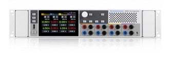
The R&S NGP800 is a DC power supply series from Rohde & Schwarz comprising five models rated at either 400 W or 800 W. Built around two or four 200 W outputs, each supplying up to 64 V or up to 20 A, the series is designed to deliver maximum power across a variety of operating points. The electrically equivalent, galvanically isolated outputs can be wired in series or parallel to reach up to 250 V or 80 A.
The series targets laboratory and automated test equipment (ATE) applications, where speed, accuracy and advanced programming features factor into test performance. A single instrument can power up to four devices under test independently, and a synchronous output button switches all channels on or off together, which is important for circuitry that can be damaged if one voltage rail is present without the other. Output delay sequencing further supports microcontrollers that require specific power-up sequences across multiple supply voltages.
ValueTronics stocks and holds its own inventory in a 20,000 square foot secure warehouse at 1675 Cambridge Drive in Elgin, Illinois, giving buyers a single accountable source for this power supply series.
Rohde & Schwarz is an independent, privately held electronics group headquartered in Munich, Germany, founded more than 80 years ago. It has operated continuously under the Rohde & Schwarz name and maintains an extensive sales and service network with locations in more than 70 countries.
The R&S NGP800 series is a single power supply family of five models that share a common architecture but differ in channel count and per-channel voltage and current ratings. Two-channel models deliver 400 W total, while four-channel models deliver 800 W; every output is rated at 200 W maximum and uses the same FlexPower approach to voltage and current within that envelope.
Because the outputs are galvanically isolated and floating, models can be operated independently or combined in series and parallel, with the family reaching up to 250 V or 80 A depending on configuration. All five share the same 5-inch touch display, protection suite, QuickArb and EasyRamp functions, data logging, and standard USB and LAN connectivity.
Each model in the R&S NGP800 series is listed below on its own dedicated product page with new-condition pricing. Select the model that matches your required channel count and voltage/current ratings, and the linked page will reflect that new configuration and its current availability.
The R&S NGP804 is the four-channel 800 W model configured as 4 x 32 V/20 A. It is the configuration the series uses to demonstrate parallel operation, reaching up to 80 A when its outputs are combined in parallel, making it the highest-current member of the family.
The models differ along three axes captured in the comparison table: number of output channels (two versus four), the per-channel voltage and current tier (32 V/20 A versus 64 V/10 A), and the maximum voltage or current reachable in series and parallel operation. The NGP802 and NGP822 are two-channel 400 W units, while the NGP804, NGP824 and NGP814 are four-channel 800 W units.
Within the four-channel group, the NGP804 provides four 32 V/20 A outputs and reaches 80 A in parallel, the NGP824 provides four 64 V/10 A outputs and reaches 250 V in series, and the NGP814 mixes two 32 V/20 A and two 64 V/10 A channels. Refer to the comparison table for the exact per-model voltage, current, series and parallel figures.
| Model | Channels | Output Voltage | Output Current |
|---|---|---|---|
| NGP814 | 4 | 32 V (CH1, CH2) / 64 V (CH3, CH4) | 20 A (CH1, CH2) / 10 A (CH3, CH4) |
| NGP802 | 2 | 0 V to 32 V | 20 A |
| NGP822 | 2 | 0 V to 64 V | 10 A |
| NGP804 | 4 | 0 V to 32 V | 20 A |
Additional differences in specifications beyond the few shown above are not listed here — see each model's full specifications below.
| Specification | Value |
|---|---|
| Outputs | |
| Number of output channels | 4 |
| Total output power | max. 800 W |
| Maximum output power per channel | 200 W |
| Output voltage per channel (CH1, CH2) | 0 V to 32 V |
| Output voltage per channel (CH3, CH4) | 0 V to 64 V |
| Maximum output current per channel (CH1, CH2) | 20 A |
| Maximum output current per channel (CH3, CH4) | 10 A |
| Maximum voltage in serial operation | 128 V |
| Maximum current in parallel operation | 40 A |
| Voltage ripple and noise (20 Hz to 20 MHz) | < 3 mV (RMS), < 30 mV (Vpp) (meas.) |
| Current ripple and noise (20 Hz to 20 MHz) | < 3.5 mA (RMS) (meas.) |
| Load regulation, voltage (CH1, CH2) ±(% of output + offset) | < 0.01 % + 5 mV |
| Load regulation, voltage (CH3, CH4) ±(% of output + offset) | < 0.01 % + 10 mV |
| Load regulation, current ±(% of output + offset) | < 0.01 % + 5 mA |
| Load recovery time (50 % to 100 % load change to within 0.2 % of rated voltage) | < 400 µs (meas.) |
| Rise time (CH1, CH2; 10 % to 90 % of rated output voltage, resistive load) | < 10 ms |
| Rise time (CH3, CH4; 10 % to 90 % of rated output voltage, resistive load) | < 12 ms |
| Fall time (CH1, CH2; 90 % to 10 % of rated output voltage, resistive load) | full load: < 10 ms, no load: < 50 ms |
| Fall time (CH3, CH4; 90 % to 10 % of rated output voltage, resistive load) | full load: < 25 ms, no load: < 50 ms |
| Programming resolution, voltage | 1 mV |
| Programming resolution, current | 0.5 mA |
| Programming accuracy, voltage (CH1, CH2) ±(% of setting + offset) | < 0.05 % + 5 mV |
| Programming accuracy, voltage (CH3, CH4) ±(% of setting + offset) | < 0.05 % + 10 mV |
| Programming accuracy, current ±(% of setting + offset) | < 0.1 % + 5 mA |
| Output measurements | |
| Measurement functions | voltage, current, power, energy |
| Readback resolution, voltage | 1 mV |
| Readback resolution, current | 0.5 mA |
| Readback accuracy, voltage (CH1, CH2) ±(% of output + offset) | < 0.05 % + 5 mV |
| Readback accuracy, voltage (CH3, CH4) ±(% of output + offset) | < 0.05 % + 10 mV |
| Readback accuracy, current ±(% of output + offset) | < 0.1 % + 5 mA |
| Temperature coefficient (per °C, CH1, CH2), +5 °C to +20 °C and +30 °C to +40 °C | voltage: < 0.0075 % + 0.75 mV, current: < 0.015 % + 0.75 mA |
| Temperature coefficient (per °C, CH3, CH4), +5 °C to +20 °C and +30 °C to +40 °C | voltage: < 0.0075 % + 1.5 mV, current: < 0.015 % + 0.75 mA |
| Remote sensing | |
| Maximum sense compensation | 1 V (meas.) |
| Ratings | |
| Maximum voltage to ground | 250 V DC |
| Maximum counter voltage (CH1, CH2; same polarity connected to the outputs) | 35 V |
| Maximum counter voltage (CH3, CH4; same polarity connected to the outputs) | 70 V |
| Maximum reverse voltage (opposite polarity connected to the outputs) | 0.4 V |
| Maximum reverse current (for 5 min max.) | 20 A |
| Remote control | |
| Command processing time | < 6 ms (typ.) |
| Protection functions | |
| Overvoltage protection | adjustable for each channel |
| OVP programming resolution | 1 mV |
| Overpower protection | adjustable for each channel |
| Overcurrent protection (electronic fuse) | adjustable for each channel |
| OCP programming resolution | 0.5 mA |
| OCP response time ((Iload > Iresp × 2) at Iload ≥ 2 A) | < 1 ms |
| Fuse linking (FuseLink function) | yes |
| Fuse delay at output-on | 10 ms to 10 s (1 ms increments) |
| Fuse delay time | 10 ms to 10 s (1 ms increments) |
| Response time for linked channels | < 5 ms |
| Overtemperature protection | independent for each channel |
| Special functions | |
| Output ramp function | EasyRamp |
| EasyRamp time | 10 ms to 60 s (1 ms increments) |
| Output delay synchronicity | < 1 ms (typ.) |
| Output delay per channel | 10 ms to 10 s (1 ms increments) |
| Arbitrary function | QuickArb |
| QuickArb parameters | voltage, current, time |
| Maximum number of points | 1024 |
| Maximum number of subgroups | 8 |
| Dwell time | 1 ms to 60 s (1 ms increments) |
| Repetition | continuous or burst mode with 1 to 65 535 repetitions |
| Trigger | manually, by remote control or via optional trigger input |
| Data logging | |
| Maximum acquisition rate | 125 sample/s |
| Memory depth | 800 Mbyte internal or external memory |
| Display and interfaces | |
| Display | TFT 5" 800 × 480 pixel WVGA touch |
| Front panel connections | 4 mm safety sockets (channel outputs, remote sensing) |
| Rear panel connections | 2 × 8-pin connector block (channel outputs and remote sensing) |
| Remote control interfaces (standard) | USB-TMC, USB-CDC (Virtual COM), LAN |
| Trigger and control interfaces | |
| R&S®NGP-K103 | digital I/O, 16-pin connector block |
| Trigger response time | < 3 ms (typ.) |
| Maximum voltage (IN/OUT) | 5.5 V |
| Input trigger level | TTL |
| Maximum drain current (OUT) | 5 mA |
| Analog control interface (R&S®NGP-K107) | analog input, 16-pin connector block |
| Input voltage (0 % to 100 % control of voltage or current) | 0 V to 5 V |
| Analog input output accuracy | CH1, CH2: voltage: < 0.1 % + 16 mV, current: < 0.1 % + 30 mA; CH3, CH4: voltage: < 0.1 % + 32 mV, current: < 0.1 % + 15 mA |
| Update rate | 1 ms |
Important: Maximum voltage to ground: 250 V DC.
Important: The IEEE-488 (GPIB) and wireless LAN interfaces are optional and not included as standard; USB and LAN (Ethernet) are the standard remote-control interfaces. The optional interfaces can be added at a later date.
Important: User adjustment (in-house calibration) requires a standard 6½ digit DMM, a 10 mΩ shunt resistor and approximately one minute per channel.
Important: The QuickArb function uses dwell times down to 1 ms; a sequence contains a maximum of 1024 points, and up to eight subgroup files can be loaded into one sequence.
Recommended pairing: install with the R&S ZZA-GE23 19-inch rack adapter (2 HU) for rack-based test systems.
This is a brand-new, factory-sealed unit, supplied exactly as it arrives from the manufacturer and backed by the full manufacturer warranty. For the exact configuration, available options, included accessories, or current lead time for your application, our Test Architects can confirm the details before you order.
ValueTronics supplies both new and used test and measurement equipment. New units ship factory-sealed, exactly as received from the manufacturer; every used unit is inspected and functionally verified in-house at our 20,000 sq ft secure facility in Elgin, Illinois before it ships. Our Test Architects can help you select the condition, calibration, and configuration that fit your application.
Please review the Manufacturer's Data Sheet to verify published specifications. Feedback on this webpage is always welcome — please reach out to your Test Architect at any time for questions or concerns. Thank you, we truly appreciate you being our customer.
Model No
Rohde
Condition
Factory New
Manufacturer
Rohde & Schwarz
Dcsup_amps
20 A / 10 A
Dcsup_volts
32 V / 64 V
Dcsup_watts
800 W

30+ Years in Business
Secure Payments
Sell Test Equipments
Knowledgeable Staff
On-site Lab
30+ Years in Business
Secure Payments
Sell Test Equipments
Knowledgeable Staff
On-site Lab
Request A Quote
 Chat Live
 Contact Us
 sales@valuetronics.com