In summary, the Keysight-era market has trained engineers to think of the power analyzer as the single defensible source of efficiency and loss data for any product whose performance specification is power. The Fluke-N4K 3PP54IP configures the Fluke Norma 4000 chassis with 3 × PP54 input modules, delivering 0.1% basic accuracy, 10 A direct current measurement (or extended-range measurement via wideband precision shunts), 341 kHz sampling, and dc to 3 MHz bandwidth across 3 fully isolated channels. The instrument is purpose-built for three-phase and multi-phase motor drive efficiency test, EV powertrain development, inverter and UPS characterization, and applications that require 0.1% basic accuracy alongside a 3 MHz bandwidth without paying for the extreme bandwidth of the PP50.
The Fluke-N4K 3PP54IP is used by power electronics engineers, motor drive developers, lighting engineers, and calibration laboratories to measure single-phase or polyphase electrical power with high precision — voltage, current, real power, reactive power, apparent power, power factor, harmonics, and efficiency — across signals ranging from dc to several MHz. Typical applications include electric motor and inverter drive system characterization, lighting ballast and LED driver test, switching power supply and UPS analysis, automotive and EV electrical efficiency measurement, transformer loss measurement, and current transducer calibration.
A DMM measures RMS voltage or current on a single channel; it cannot resolve the complex relationship between voltage and current that defines real, reactive, and apparent power on a non-sinusoidal waveform. The Fluke-N4K 3PP54IP acquires all 3 phases in parallel at 341 kHz, calculates true power from the integrated product of instantaneous voltage and current samples, performs FFT harmonic analysis to the 40th order, and maintains specified accuracy with all inputs galvanically isolated — making it suitable for the switching waveforms present on variable frequency drives and high-efficiency lighting loads where a DMM and clamp meter would produce misleading results.
The Fluke-N4K 3PP54IP delivers 0.1% basic accuracy on voltage, current, and power with the PP54 power phase module, 341 kHz sampling rate, and dc to 3 MHz bandwidth (3 MHz via BNC, 1 MHz direct measured). Voltage input range spans 0.3 V to 1000 V across 8 ranges with 2 MOhm / 20 pF input impedance and 120 dB common mode rejection at 100 kHz. Current measurement covers 30 – 100 mA – 0,3 – 1 – 3 – 10 A via integrated wideband shunts, with overload capability of max. 15 A continuous, 30 A < 5 sec / 15 sec no load, 100 A < 0.1 s / 30 sec no load. Harmonics are calculated to the 40th order, and the instrument maintains its industry-leading two-year recalibration interval — twice the cycle of most competing power analyzers — reducing the cost of compliance for laboratories operating under ISO 9001, ISO 17025, AS9100, or FDA 21 CFR 820 quality systems.
Fluke Corporation, founded in 1948 and now part of Fortive, is the brand most associated with trustworthy electrical measurement in field, industrial, and laboratory environments. The Fluke Norma 4000 and 5000 product line represents the company's high-precision power analyzer platform, addressing the same engineering problems served by the Yokogawa WT3000E/WT5000 and Hioki PW6001 — measuring efficiency, harmonics, and loss in motor drives, inverters, lighting equipment, transformers, and switching power supplies. Norma-series instruments are referenced in efficiency standards documentation that aligns with IEC 61010 (safety), IEC 61326 (EMC), IEC 61000-3-2 (harmonic emissions limits), and IEC 61683 (efficiency measurement methodology for inverters and power conditioning systems). The Norma chassis is rated 1000 V CAT II / 600 V CAT III with Class I safety and pollution degree 2.
| Item | Description |
|---|---|
| Power supply cable | Country-appropriate mains cable |
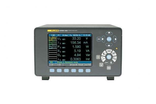
| Color display | 5.7" / 144 mm, 320 × 240 pixel, user-selectable backlighting and contrast — integrated |
| RS232 / USB interface | For firmware upload and data download (standard) |
| Chassis configuration | Space for three power-phases and options |
| Fluke NormaView PC software | For instrument setup, data download, harmonics and waveform analysis, and report writing |
| Color user's manual | Printed manual |
| Test certificate | Factory test certificate |
| Calibration values | Factory calibration values record |
The compact Fluke Norma 4000 platform consolidates the latest power measurement technology into a single chassis sized to fit on a bench or to be carried into the field. Patented high-bandwidth architecture delivers precise measurements of single-phase or polyphase current and voltage, harmonics analysis, Fast Fourier Transformation (FFT) analysis, and the calculations of power and derived values — with class-leading accuracy and common-mode rejection for any waveform, frequency, or phase shift.
The Fluke-N4K 3PP54IP configures this chassis with 3 × PP54 power phase input modules. Each PP54 module is a fully isolated voltage-and-current measurement channel with 0.1% basic accuracy, dc to 3 MHz bandwidth, 341 kHz sampling, and direct current input up to 10 A. The base unit accepts up to three power-phase modules in total, plus optional interface cards.
| Sum limit of error | U | I |
|---|---|---|
| Range | 0.05% | 0.05% |
| Reading | 0.05% | 0.05% |
| Input level (%) | Sum limit of error U (%) | Sum limit of error I (%) |
|---|---|---|
| 100 | 0.10 | 0.10 |
| 50 | 0.15 | 0.15 |
| 30 | 0.22 | 0.22 |
| 10 | 0.55 | 0.55 |
| 5 | 1.05 | 1.05 |
| 3 | 1.72 | 1.72 |
| 1 | 5.05 | 5.05 |
| Between U and IBNC | Between U and IShunt | |
|---|---|---|
| Angular Error | 0.005° + 0.005°/kHz | 0.025° + 0.015°/kHz |
Aliasing filter OFF. Valid for averaged values at 23 ± 0.5 °C ambient temperature, sine waveform, and after 1 hour turn-on time with measuring signal.
| Frequency (Hz) | Limit of error power (%) |
|---|---|
| 45 | 0.16 / –0.16 |
| 65 | 0.16 / –0.16 |
Non-gapping calculation of averaged values for each phase. In a three-phase system, total power is also calculated, plus the averaging of V and I across the three phases. The fundamental H01 is calculated in synchronous mode for these values.
| Range | DC and 0.2 Hz to sampling rate |
| Accuracy | ±0.01% of measured value (reading) |
| Channel selection | All U/I or external input |
| Filtering | Selectable low-pass filter (one of three frequencies) |
| Display | Frequency always visible at the top of the screen |
| BNC sync socket (rear) | Input or output mode; input max level 50 V; output is pulsed 5 V TTL (frequency depends on measured sync frequency) |
| Working temperature range | 5 °C to 35 °C (41 °F to 95 °F) |
| Storage temperature range | –20 °C to 50 °C (–4 °F to 122 °F) |
| Housing | Solid metal case to meet stringent EMC requirements |
| Weight (base unit) | approx. 5 kg (11 lb.) |
| Size (H × W × D) | 15 cm × 23.7 cm × 31.5 cm (5.9 in. × 9.3 in. × 12.4 in.) |
| Display | 5.7" / 144 mm — 320 × 240 pixel; user-selectable background lighting and contrast |
| Climatic class | KYG DIN 40040, max. 85% relative humidity, non-condensing |
| Mains connection | 85 to 264 V ac, 50 to 60 Hz; dc 100 to 260 V; approx. 40 VA; European plug with switch |
| Measuring inputs | Safety sockets 4 mm, 2 for each input; external shunt connection over BNC socket |
| Operation | Membrane keyboard with cursor — function keys and direct functions |
| Electrical safety | EN 61010-1 / 2nd Edition 1000 V CAT II (600 V CAT III); degree of pollution 2; safety Class I; EN 61558 for transformer; EN 61010-2-031/032 for accessories |
| Maximum voltage input | Measurement range 1000 Veff, 2 kVpeak |
| Maximum current input | Measurement range 10 Aeff or 20 Aeff (module-dependent), 20 Apeak |
| Test voltages | Mains input – case (protective conductor): 1.5 kV ac; mains – measurement input: 5.4 kV ac; measurement inputs – case: 3.3 kV ac; measurement input – measurement input: 5.4 kV |
| EMC | Emission: IEC 61326-1, EN 50081-1, EN 55011 Class B; Immunity: IEC 61326-1 / Annex A (industrial sector), EN 50082-1 |
| Recommended recalibration | 2 years (industry's longest interval) |
The input modules can take up to 10 A or 20 A directly (module-dependent) or measure current via wideband precision shunts. The available range of shunts enables measurements up to 1500 A and can be used in conjunction with all of the available input modules.
| Order Number | Description |
|---|---|
| 3024677 | 32 A Planar Shunt |
| 3024689 | Cables for 32 A Planar Shunt |
| 3024886 | 10 A Triaxial Shunt with Cables (0.333 Ω, 0 to 0.5 MHz) |
| 3024899 | 30 A Triaxial Shunt with Cables (0.010 Ω, 0 to 0.5 MHz) |
| 3024847 | 100 A Shunt with Cables (0.001 Ω, 0 to 0.5 MHz) |
| 3024858 | 150 A Shunt with Cables (0.5 mΩ, 0 to 0.5 MHz) |
| 3024864 | 300 A Shunt with Cables (0.1 mΩ, 0 to 1 MHz) |
| 3024873 | 500 A Shunt with Cables (0.1 mΩ, 0 to 0.2 MHz) |
| 3024692 | LG Shunt Cables for High Current Shunts |
| 3024661 | Measurement Cable Set (for one power phase) |
| 3024704 | Fluke Norma WYE Adaptor (external accessory box) |
All accessories have a two-year warranty.
Model No
N4K
Condition
New
Manufacturer
Fluke

30+ Years in Business
Secure Payments
Sell Test Equipments
Knowledgeable Staff
On-site Lab
30+ Years in Business
Secure Payments
Sell Test Equipments
Knowledgeable Staff
On-site Lab
Request A Quote
 Chat Live
 Contact Us
 sales@valuetronics.com