

🎓 Request a Quote To Get An EDU Discount
Couldn't load pickup availability
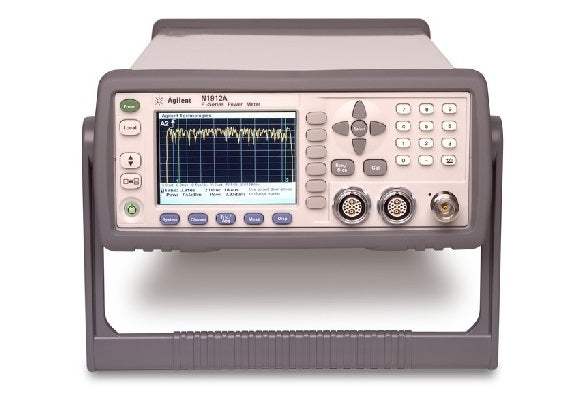
The Agilent N1911A and N1912A are P-Series peak power meters paired with the N1921A and N1922A P-Series wideband power sensors. Each meter is an LXI Class-C-compliant instrument developed using LXI (LAN eXtension for Instrumentation) technology, which uses Ethernet (LAN) as its primary communication interface. An integrated Web browser provides a convenient way to configure the instrument's functionality. The N1911A is a single-channel meter and the N1912A is a dual-channel meter, while the N1921A and N1922A wideband sensors cover frequency ranges of 50 MHz to 18 GHz and 50 MHz to 40 GHz respectively.
A power meter and sensor combination measures the power level of an RF or microwave signal — one of the most fundamental quantities characterized on a high-frequency test bench. This combination provides average, peak, and peak-to-average ratio power measurements with both free-run and time-gated definitions. It also performs time-parameter measurements, including pulse rise time, fall time, pulse width, time-to-positive occurrence, and time-to-negative occurrence.
ValueTronics stocks and holds its own inventory in a 20,000-square-foot secure warehouse at 1675 Cambridge Drive in Elgin, Illinois. Every pre-owned unit is inspected and functionally verified in-house before it ships, while new units ship factory-sealed exactly as received from the manufacturer. This combination of held inventory and in-house verification lets engineers source the right P-Series instrument with confidence in its condition.
Agilent Technologies was established in 1999 as a spin-off of Hewlett-Packard's test and measurement business. In 2014, that test and measurement operation was separated again to form Keysight Technologies, which carries the lineage forward today.
The P-Series family pairs peak power meters with wideband power sensors. The meter is offered in two configurations — the single-channel N1911A and the dual-channel N1912A — and both are LXI Class-C-compliant instruments that use Ethernet (LAN) as their primary communication interface. The wideband sensors, the N1921A and N1922A, attach to either meter to form a complete measurement system.
Across the family, the meters share the same core measurement architecture — average, peak, and peak-to-average ratio power, plus pulse time-parameter measurements — and the same 100 Msamples/sec continuous sampling. The models differ primarily in channel count on the meter side and in frequency coverage and connector type on the sensor side, as the comparison table details.
Each model below links to its own dedicated product page with condition-matched pricing for the pre-owned unit you select. Choose the meter channel count and the sensor frequency range that match your application, and review each model's page for its specific configuration.
On the meter side, the N1911A is a single-channel peak power meter while the N1912A is a dual-channel peak power meter; the dual-channel unit also carries a higher power requirement, not exceeding 75 VA (50 W) versus 50 VA (30 W) for the single-channel meter.
On the sensor side, the N1921A covers 50 MHz to 18 GHz with a Type N (m) connector and an average power measurement accuracy of ≤ ± 0.2 dB or ± 4.5 %, while the N1922A extends coverage to 50 MHz to 40 GHz with a 2.4 mm (m) connector and an accuracy of ≤ ± 0.3 dB or ± 6.7 %. Both sensors share the same –35 dBm to +20 dBm dynamic range above 500 MHz and the same damage levels. See the comparison table for the full breakdown.
| Model | Type | Channels | Frequency Range |
|---|---|---|---|
| N1912A | Power Meter | 2 | — |
| N1911A | Power Meter | 1 | — |
| N1911A | Power Meter | 1 | — |
| N1921A | Power Sensor | — | 50 MHz to 18 GHz |
Additional differences in specifications beyond the few shown above are not listed here — see each model's full specifications below.
| Specification | Value |
|---|---|
| General Features | |
| Number of channels | Dual channel |
| Key System Specifications and Characteristics | |
| Maximum sampling rate | 100 Msamples/sec, continuous sampling |
| Video bandwidth | ≥ 30 MHz |
| Single-shot bandwidth | ≥ 30 MHz |
| Rise time and fall time | ≤ 13 ns (for frequencies ≥ 500 MHz) |
| Minimum pulse width | 50 ns |
| Overshoot | ≤ 5 % |
| Average power measurement accuracy (N1921A) | ≤ ± 0.2 dB or ± 4.5 % |
| Average power measurement accuracy (N1922A) | ≤ ± 0.3 dB or ± 6.7 % |
| Dynamic range | –35 dBm to +20 dBm (> 500 MHz); –30 dBm to +20 dBm (50 MHz to 500 MHz) |
| Maximum capture length | 1 second |
| Maximum pulse repetition rate | 10 MHz (based on 10 samples per period) |
| Meter Uncertainty | |
| Instrumentation linearity | ± 0.8 % |
| Timebase | |
| Timebase range | 2 ns to 100 msec/div |
| Accuracy | ±10 ppm |
| Jitter | ≤ 1 ns |
| Trigger — Internal Trigger | |
| Range | –20 to +20 dBm |
| Resolution | 0.1 dB |
| Level accuracy | ± 0.5 dB |
| Latency | 160 ns ± 10 ns |
| Jitter | ≤ 5 ns rms |
| External TTL Trigger Input | |
| High | > 2.4 V |
| Low | < 0.7 V |
| Latency | 90 ns ± 10 ns |
| Minimum trigger pulse width | 15 ns |
| Minimum trigger repetition period | 50 ns |
| Maximum trigger voltage input | 15 V emf from 50 Ω dc (current < 100 mA), or 60 V emf from 50 Ω (pulse width < 1 s, current < 100 mA) |
| Impedance | 50 Ω |
| Jitter | ≤ 5 ns rms |
| External TTL Trigger Output | |
| High | > 2.4 V |
| Low | < 0.7 V |
| Latency | 30 ns ± 10 ns |
| Impedance | 50 Ω |
| Jitter | ≤ 5 ns rms |
| Trigger Delay | |
| Delay range | ± 1.0 s, maximum |
| Delay resolution | 1 % of delay setting, 10 ns maximum |
| Trigger Hold-off | |
| Range | 1 μs to 400 ms |
| Resolution | 1 % of selected value (to a minimum of 10 ns) |
| Trigger Level Threshold Hysteresis | |
| Range | ± 3 dB |
| Resolution | 0.05 dB |
| Dynamic Response — Rise/Fall Time and Overshoot vs Video Bandwidth | |
| Rise time/fall time (Low: 5 MHz) | < 56 ns |
| Rise time/fall time (Medium: 15 MHz) | < 25 ns |
| Rise time/fall time (High: 30 MHz) | ≤ 13 ns |
| Rise time/fall time (Off, < 500 MHz) | < 36 ns |
| Rise time/fall time (Off, > 500 MHz) | ≤ 13 ns |
| Overshoot | < 5 % |
| 1 mW Power Reference | |
| Power output | 1.00 mW (0.0 dBm). Factory set to ± 0.4 % traceable to the National Physical Laboratory (NPL) UK |
| Accuracy (over 2 years) | ±1.2 % (0 to 55 ºC); ±0.4 % (25 ± 10 ºC) |
| Frequency | 50 MHz nominal |
| SWR | 1.08 (0 to 55 ºC); 1.05 typical |
| Connector type | Type N (f), 50 Ω |
| Rear-panel Inputs/Outputs | |
| Recorder output | Analog 0-1 Volt, 1 kΩ output impedance, BNC connector. For dual-channel instruments there will be two recorder outputs. |
| GPIB, 10/100BaseT LAN and USB2.0 | Interfaces allow communication with an external controller |
| Ground | Binding post, accepts 4 mm plug or bare-wire connection |
| Trigger input | TTL compatible logic levels, BNC connector |
| Trigger output | TTL compatible logic levels, BNC connector |
| Line Power | |
| Input voltage range | 90 to 264 Vac, automatic selection |
| Input frequency range | 47 to 63 Hz and 440 Hz |
| Power requirement | Not exceeding 75 VA (50 Watts) |
| Remote Programming | |
| Interface | GPIB (IEEE 488.2 and IEC65); 10/100BaseT LAN; USB 2.0 |
Important: Maximum trigger voltage input: 15 V emf from 50 Ω dc (current < 100 mA), or 60 V emf from 50 Ω (pulse width < 1 s, current < 100 mA).
Important: A P-Series wideband power sensor (N1921A or N1922A) is required to make power measurements; the sensor is ordered separately and is not included in the N1911A/N1912A power meter's standard-shipped accessories.
Important: The P-Series wideband power sensors are designed for use with the P-Series power meters only.
Important: The 1 mW power reference is provided for calibration of E-Series, 8480 Series and N8480 Series sensors. The P-Series sensors are automatically calibrated and therefore do not need this reference for calibration.
Important: Although the rise time specification is ≤ 13 ns, this does not mean the P-Series meter and sensor combination can accurately measure a signal with a known rise time of 13 ns; the measured rise time is the root sum of the squares (RSS) of the signal-under-test rise time and the 13 ns system rise time.
Important: The Off video bandwidth setting provides the warranted rise time and fall time specification and is the recommended setting for minimizing overshoot on pulse signals. For Option 107 (10 m cable), add 5 ns to the rise time and fall time specifications.
This pre-owned unit is inspected and functionally verified in-house before it ships and is backed by our pre-owned warranty. To confirm its exact condition, firmware revision, installed options, or included accessories for your application before ordering, contact our Test Architects.
ValueTronics supplies both new and used test and measurement equipment. New units ship factory-sealed, exactly as received from the manufacturer; every used unit is inspected and functionally verified in-house at our 20,000 sq ft secure facility in Elgin, Illinois before it ships. Our Test Architects can help you select the condition, calibration, and configuration that fit your application.
Please review the Manufacturer's Data Sheet to verify published specifications. Feedback on this webpage is always welcome — please reach out to your Test Architect at any time for questions or concerns. Thank you, we truly appreciate you being our customer.
Model No
Agilent
Condition
Pre-Owned
Manufacturer
Keysight Technologies
N1917B Agilent Cable Used
N1917B
N1917A Agilent Cable Used
N1917A

30+ Years in Business
Secure Payments
Sell Test Equipments
Knowledgeable Staff
On-site Lab
30+ Years in Business
Secure Payments
Sell Test Equipments
Knowledgeable Staff
On-site Lab
Request A Quote
 Chat Live
 Contact Us
 sales@valuetronics.com
