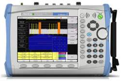
The Anritsu Cell Master MT8212B is a comprehensive, one-box base station test tool for deploying, maintaining, and troubleshooting wireless base stations. It consolidates a cable and antenna analyzer (25 MHz to 4.0 GHz), spectrum analyzer (100 kHz to 3.0 GHz), power meter (4.5 MHz to 3.0 GHz), interference analyzer, channel scanner, transmission analyzer for 2-port devices, transmitter analyzer for CDMA and GSM, GPS receiver, and T1/E1 analyzer into a single lightweight, handheld test set - eliminating the need for a field engineer or technician to carry, manage, and learn multiple test sets.
Across its measurement modes the MT8212B performs precision return loss, VSWR, cable loss, and distance-to-fault measurements, along with signal identification, interference analysis, channel power, adjacent channel power ratio, field strength, occupied bandwidth, burst power, code domain power, noise floor, and voltage peak-to-peak. It can also listen to DS0 or VF channel access. Patented RF interference rejection enables accurate, repeatable measurements in the presence of high RF activity, and built-in GPS stores traces with location information (latitude, longitude, and altitude).
ValueTronics stocks and holds its own inventory in a 20,000 sq ft secure warehouse at 1675 Cambridge Drive in Elgin, Illinois, so the instrument you order is handled and shipped from our own facility. Every pre-owned unit is inspected and functionally verified in-house before it ships, while new units ship factory-sealed exactly as received from the manufacturer.
| Specification | Value |
|---|---|
| Cable and Antenna Analyzer | |
| Frequency Range | 25 MHz to 4.0 GHz |
| Frequency Accuracy | ≤± 75 ppm @ +25°C |
| Resolution | 100 kHz |
| Output Power | < 0 dBm (–10 dBm nominal) |
| Immunity to Interfering Signals (on-channel) | +17 dBm |
| Immunity to Interfering Signals (on-frequency) | –5 dBm |
| Measurement speed | ≤3.5 msec / data point (CW ON) |
| Number of data points | 130, 259, 517 |
| Return Loss Range | 0.00 to 60.00 dB |
| Return Loss Resolution | 0.01 dB |
| VSWR Range | 1.00 to 65.00 |
| VSWR Resolution | 0.01 |
| Cable Loss Range | 0.00 to 30.00 dB |
| Cable Loss Resolution | 0.01 dB |
| Measurement Accuracy | > 42 dB corrected directivity after calibration |
| Distance-To-Fault Vertical Range | Return Loss: 0.00 to 60.00 dB; VSWR: 1.00 to 65.00 |
| Distance-To-Fault Horizontal Range | Range: 0 to (# of data pts –1) x Resolution to a maximum of 1197m (3929 ft), # of data pts = 130, 259, 517 |
| Distance-To-Fault Horizontal Resolution (Rectangular windowing) | Resolution (meter) = (1.5 x 10^8) x (Vp)/DF, where Vp is the cable's relative propagation velocity and where DF is the stop frequency minus the start frequency (in Hz) |
| Spectrum Analyzer | |
| Reference (Internal Timebase) | Aging: ± 1 ppm/yr; Accuracy: ± 2 ppm |
| Span | 10 Hz to 2.99 GHz in 1, 2, 5 step selections in auto mode, plus zero span |
| Sweep Time | ≤1.1 sec full span; ≤50 µsec to 20 sec zero span |
| Resolution Bandwidth (–3 dB) | 100 Hz to 1 MHz in 1-3 sequence ± 5% Accuracy |
| Video Bandwidth (–3 dB) | 3 Hz to 1 MHz in 1-3 sequence ± 5% Accuracy |
| SSB Phase Noise (1 GHz) @ 30 kHz Offset | ≤–75 dBc/Hz |
| Spurious Responses Input Related | ≤–45 dBc |
| Spurious Residual Responses | ≤–90dBm, ≥10 MHz (10 kHz RBW, pre-amp on) |
| Total Level Accuracy | ±1 dB typical (±1.5 dB max), >10 MHz to 3 GHz; ±2 dB typical <10 MHz for input signal levels ≥–60 dBm, excluding input VSWR mismatch |
| Measurement Range | +20 dBm to –135 dBm |
| Input Attenuator Range | 0 to 51 dB, selected manually or automatically coupled to the reference level. Resolution in 1 dB steps. |
| Displayed Average Noise Level | ≤–135 dBm, >10 MHz (preamp on); ≤–115 dBm (preamp off) for input terminated, 0 dB attenuation, RMS detection, 100 Hz RBW |
| Dynamic Range | >65 dB typical |
| Display Range | 1 to 15 dB/division, in 1 dB steps, 10 divisions displayed |
| Scale Units | dBm, dBV, dBmV, dBµV, V, W |
| RF Input VSWR | (with 20 dB atten.) 1.5:1 typical, (10 MHz to 2.4 GHz) |
| Power Meter | |
| Frequency Range | 4.5 MHz to 3.0 GHz |
| Display Range | –80 dBm to +80 dBm |
| Offset Range | 0 to +60 dB |
| Accuracy | ±1 dB typical (±1.5 dB max), ≥10 MHz to 3 GHz (excludes input VSWR) |
| VSWR | 1.5:1 typical (Pin > –30 dBm, >10 MHz to 2.4 GHz) |
| Measurement Range | –80 dBm to +20 dBm (+80 dBm with external attenuator) |
| Maximum Power | 20 dBm (0.1W) without external attenuator |
| T1 Analyzer (Option 50) | |
| Line Coding | AMI, B8ZS |
| Framing Modes | D4 (Superframe), ESF (Extended Superframe) |
| Connection Configurations | Terminate (100 Ω); Bridge (≥1000 Ω); Monitor (Connect via 20 dB pad in DSX) |
| Receiver Sensitivity | 0 to –36 dBdsx |
| Transmit Level | 0 dB, –7.5 dB, and –15 dB |
| Clock Sources | External; Internal: 1.544 MHz ± 30 ppm |
| Pulse Shapes | Conform to ANSI T1.403 |
| Pattern Generation and Detection | PRBS: 2-9, 2-11, 2-15, 2-20, 2-23 Inverted and non-inverted, QRSS, 1-in-8 (1-in-7), 2-in-8, 3-in-24, All ones, All zeros, T1-Daly, User defined (≤32 bits) |
| Circuit Status Reports | Carrier present, Frame ID and Sync., Pattern ID and Sync. |
| Alarm Detection | AIS (Blue Alarm), RAI (Yellow Alarm) |
| Error Detection | Frame Bits, Bit, BER, BPV, CRC, Error Sec |
| Error Insertion | Bit, BPV, Framing Bits, RAI, AIS |
| Loopback Modes | Self loop, CSU, NIU, User defined, In-band or Data Link |
| Level Measurements | Vp-p (± 5%) |
| Data Log | Continuous, up to 48 hrs |
| E1 Analyzer (Option 50) | |
| Line Coding | AMI, HDB3 |
| Framing Modes | PCM30, PCM30CRC, PCM31, PCM31CRC |
| Connection Configurations | Terminate (75, 120 Ω); Bridge (≥1000 Ω); Monitor (Connect via 20 dB pad in DSX) |
| Receiver Sensitivity | 0 to –43 dB |
| Clock Sources | External; Internal 2.048 MHz ± 30 ppm |
| Pulse Shapes | Conform to ITU G.703 |
| Pattern Generation and Detection | PRBS: 2-9, 2-11, 2-15, 2-20, 2-23 Inverted and non-inverted, QRSS, 1-in-8 (1-in-7), 2-in-8, 3-in-24, All ones, All zeros, T1-Daly, User defined (≥32 bits) |
| Circuit Status Reports | Carrier present, Frame ID and Sync., Pattern ID and Sync. |
| Alarm Detection | AIS, RAI, MMF |
| Error Detection | Frame Bits, Bit, BER, BPV, CRC, E-Bits, Error Sec |
| Error Insertion | Bit, BPV, Framing Bits, RAI, AIS |
| Loopback Modes | Self loopback |
| Level Measurements | Vp-p (± 5%), can also display in dBdsx |
| Data Log | Continuous, up to 48 hrs |
| Audio | Standard speaker and headphone jack |
| Transmission Measurement (Option 21) – RF Source | |
| Frequency Range | 25 MHz to 3 GHz |
| Frequency Resolution | 10 Hz |
| Output Power Level | –10 dBm typical (up to –90 dBm with external attenuator) |
| Dynamic Range | 80 dB, 25 MHz to 1 GHz; 60 dB, >1 GHz to 3 GHz |
| Output Impedance | 50 Ω |
| RF Measurements - GSM (Option 40) | |
| Occupied Bandwidth | Bandwidth within which 0-99% of the power transmitted on a single channel lies or 0 to –120 dBc to the down the skirts of the signal. |
| Burst power | ±1 dB typical for –20 dBm to +20 dBm (±1.5 dB max); ±1.75 dB typical for –80 dBm to –20 dBm (±2 dB max) |
| Frequency error | ±10 Hz + Time base error |
| RF Measurements - CDMA (Option 42) | |
| Channel power | ±1 dB typical (±1.5 dB max) |
| Carrier frequency | 99% confidence level |
| Frequency Range | 100 kHz to 3.0 GHz |
Important: Maximum RF In without damage: +43 dBm (peak), +-50 VDC. Maximum RF Out without damage: +20 dBm, +-50 VDC.
Important: All specifications apply when calibrated at ambient temperature after a five minute warm up.
Important: Interference Analyzer (Option 25) requires a directional antenna.
Important: cdmaOne and cdma2000 1xRTT Over The Air (Option 33) requires Options 31 and 43.
Important: Test port cables and calibration components (such as the ICN50 InstaCal Calibration Module or a precision Open/Short/Load) needed to perform cable and antenna analyzer measurements are not part of the standard accessories; they are listed under Optional Accessories and must be ordered separately.
Important: For any prolonged non-operating storage period, it is recommended that the battery be stored separately between 0°C to +40°C.
This pre-owned unit is inspected and functionally verified in-house before it ships and is backed by our pre-owned warranty. To confirm its exact condition, firmware revision, installed options, or included accessories for your application before ordering, contact our Test Architects.
ValueTronics supplies both new and used test and measurement equipment. New units ship factory-sealed, exactly as received from the manufacturer; every used unit is inspected and functionally verified in-house at our 20,000 sq ft secure facility in Elgin, Illinois before it ships. Our Test Architects can help you select the condition, calibration, and configuration that fit your application.
Please review the Manufacturer's Data Sheet to verify published specifications. Feedback on this webpage is always welcome — please reach out to your Test Architect at any time for questions or concerns. Thank you, we truly appreciate you being our customer.
Model No
Anritsu
Condition
Pre-Owned
Manufacturer
Anritsu
Cabant_ana_freq
25 MHz to 4.0 GHz

30+ Years in Business
Secure Payments
Sell Test Equipments
Knowledgeable Staff
On-site Lab
30+ Years in Business
Secure Payments
Sell Test Equipments
Knowledgeable Staff
On-site Lab
Request A Quote
 Chat Live
 Contact Us
 sales@valuetronics.com