In summary, the Tektronix MSO54B reviewed here is a 2 GHz, 4-channel mixed signal oscilloscope from the 5 Series B family, shipped with bandwidth option 5-BW-2000 already enabled. The instrument is built on FlexChannel® technology that lets each input be configured as one analog channel, eight digital logic channels (with a TLP058 logic probe), or simultaneous analog and spectral views with independent controls per domain. Headline specifications: 2 GHz analog bandwidth with a 225 ps calculated rise time, 6.25 GS/s real-time sample rate on all channels, 62.5 Mpoints standard record length (upgradable to 500 Mpoints), a 12-bit ADC that extends to 16 bits in High Res mode, >500,000 waveforms/sec capture rate, and a 15.6-inch high-definition (1,920 × 1,080) multi-touch display — the largest in the industry.
The Tektronix MSO54B is used by electronics design engineers, embedded systems developers, power electronics designers, and production test teams to visualize and characterize electrical signals as waveforms — voltage plotted against time. With four FlexChannel inputs and up to 32 digital channels, it covers embedded systems debugging, multi-rail power supply characterization, and general mixed-signal design work where four analog channels are sufficient. The 2 GHz bandwidth on this specific variant serves the most demanding signal-integrity, automotive Ethernet (1000BASE-T1), advanced power-electronics (SiC and GaN), and high-speed digital compliance applications in the platform.
FlexChannel technology is the central differentiator. Each channel input can serve as an analog channel, eight digital logic channels, or simultaneous analog plus spectral views — and the configuration can be changed at any time simply by adding or removing TLP058 logic probes. Unlike previous-generation MSOs that forced tradeoffs (digital channels with lower sample rates or shorter record lengths than analog channels), the 5 Series B MSO gives digital channels the same 6.25 GS/s sample rate and 500 Mpoints maximum record length as analog channels. Spectrum View — a Tektronix-patented dual-acquisition-path technology — provides true simultaneous time- and frequency-domain analysis with independent controls in each domain, eliminating the FFT tradeoffs that plague conventional oscilloscope spectrum analysis.
The Tektronix MSO54B reviewed here delivers 4 FlexChannel inputs, up to 32 digital channels with TLP058 logic probes, 2 GHz analog bandwidth with a 225 ps calculated rise time, 6.25 GS/s real-time sample rate on all channels, and 62.5 Mpoints standard record length on all channels (upgradable to 125, 250, or 500 Mpoints). The 12-bit ADC delivers 16 times the vertical resolution of traditional 8-bit oscilloscopes — at a 400 V full-scale range, that is 97.6 millivolts per count on the 12-bit ADC versus 1.56 volts per count on an 8-bit ADC, and 24.4 millivolts per count when High Res mode extends resolution to 14 bits at 625 MS/s. Waveform capture rate exceeds 500,000 waveforms/s standard, with FastFrame segmented memory enabling more than 5,000,000 trigger events per second. The 15.6-inch 1,920 × 1,080 multi-touch display provides 100% more display area than a scope with a 10.4-inch display.
Tektronix was founded in Beaverton, Oregon in 1946 by Howard Vollum and Jack Murdock, and invented the triggered oscilloscope — the instrument that made modern electronics development reproducible. For decades, "oscilloscope" and "Tektronix" have been functionally synonymous in engineering labs worldwide; Tektronix is the most recognized oscilloscope brand globally and has the deepest used oscilloscope market of any manufacturer. The 5 Series B MSO complies with the IEC 61010 safety framework (UL approval for the USA and Canada, CE marking for the European Union), is RoHS compliant, supports LXI Core 2011 over its standard 10/100/1000BASE-T Ethernet port, and complies with IEEE Standard 488.1-1987 and RS-232-C interface standards. Optional security option 5-SEC provides National Industrial Security Program Operating Manual (NISPOM) DoD 5220.22-M, Chapter 8 compliance for instruments deployed in classified environments. The instrument is registered to ISO 9001 and ISO 14001 by SRI Quality System Registrar.
The oscilloscope is the heart of the engineer's bench. It is the instrument that translates invisible electricity into a picture an engineer can reason about — voltage plotted against time, with every distortion, glitch, edge, and ripple made visible. Among all test and measurement categories, oscilloscopes appear in the widest range of design conversations, and the Tektronix 5 Series B MSO sits in the most demanding tier of that market — the tier where signal fidelity, channel density, and analysis depth all matter at once. Per the Tektronix datasheet, the 5 Series B MSO is built on a single thesis: "The largest display. The most channels. The greatest experience."
The Tektronix MSO54B reviewed here is the 2 GHz, 4-channel configuration in the 5 Series B family — shipped with bandwidth option 5-BW-2000 already enabled, no separate upgrade required. With four FlexChannel inputs (and up to 32 digital channels with TLP058 logic probes), the MSO54B is the entry point to the 5 Series B family — the right configuration when the project requires the 5 Series B's signal-fidelity advantages but four analog channels are sufficient for the application. The 5 Series B MSO redefines what a Mixed Signal Oscilloscope should be: FlexChannel technology enables each channel input to be used as a single analog channel, eight digital logic inputs (with the TLP058 logic probe), or simultaneous analog and spectrum views with independent acquisition controls for each domain. Imagine the flexibility and configurability this provides.
At 2 GHz analog bandwidth with a 225 ps calculated rise time, this configuration is the top of the 5 Series B family — the right answer for Gigabit Ethernet, 1000BASE-T1 Automotive Ethernet compliance, PCIe Gen 2, advanced power-electronics switching analysis on the fastest SiC and GaN devices, and any signal where edges as fast as a few hundred picoseconds must reproduce faithfully on screen. The 2 GHz variant is required for the 1000BASE-T1 Automotive Ethernet automated compliance test solution (5-CMAUTOEN) and for USB 2.0 high-speed compliance testing (5-CMUSB2).
Every MSO54B ships with the following accessories per the Tektronix datasheet:
Many applications, such as embedded systems, three-phase power electronics, automotive electronics, power supply design, and DC-to-DC power converters, require the observation of more than four analog signals to verify and characterize device performance, and to debug challenging system issues. Most engineers can recall situations in which they were debugging a particularly difficult problem and wanted greater system visibility and context, but the scope they were using was limited to two or four analog channels. Using a second scope involves significant effort to align trigger points, difficulty in determining timing relationships across the two displays, and documentation challenges.
And while you might assume that a six and eight channel scope would cost 50% or 100% more than a four-channel scope, you'll be pleasantly surprised to find that six channel models are only ~25% more than four channel models and eight channel models are only ~67% more than four channel models. The additional analog channels can pay for themselves quickly by enabling you to keep current and future projects on schedule.
You can change the configuration at any time by simply adding or removing TLP058 logic probes, so you always have the right number of digital channels. Previous-generation MSOs required tradeoffs, with digital channels having lower sample rates or shorter record lengths than analog channels. The 5 Series B MSO offers a new level of integration of digital channels: digital channels share the same high sample rate (up to 6.25 GS/s), and long record length (up to 500 M points) as analog channels.
The 5 Series B MSO provides the performance to capture the signals of interest while minimizing the effects of unwanted noise when you need to capture high-amplitude signals while seeing smaller signal details. At the heart of the 5 Series B MSO are 12-bit analog-to-digital converters (ADCs) that provide 16 times the vertical resolution of traditional 8-bit ADCs.
A new High Res mode applies a hardware-based unique Finite Impulse Response (FIR) filter based on the selected sample rate. The FIR filter maintains the maximum bandwidth possible for that sample rate while preventing aliasing and removing noise from the oscilloscope amplifiers and ADC above the usable bandwidth for the selected sample rate. High Res mode always provides at least 12 bits of vertical resolution and extends all the way to 16 bits of vertical resolution at ≤125 MS/s sample rates. New lower-noise front end amplifiers further improve the 5 Series B MSO's ability to resolve fine signal detail.
This vertical-resolution advantage is the differentiator that matters most for power-electronics, EV, motor-drive, and high-voltage switching supply work, where engineers must measure millivolt-level switching ripple riding on top of hundreds-of-volts bus voltages — measurements an 8-bit oscilloscope physically cannot resolve.
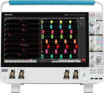
The stunning 15.6" (396 mm) display in the 5 Series B MSO is the largest display in the industry, providing 100% more display area than a scope with a 10.4" (264 mm) display. It is also the highest resolution display, with full HD resolution (1,920 × 1,080), enabling you to see many signals at once with ample room for critical readouts and analysis. The viewing area is optimized to ensure that the maximum vertical space is available for waveforms. The Results Bar on the right can be hidden, enabling the waveform view to use the full width of the display.
The 5 Series B MSO offers a revolutionary new Stacked display mode. Historically, scopes have overlaid all waveforms in the same graticule, forcing difficult tradeoffs between making each waveform visible (which used a small percentage of the available ADC range, leading to less accurate measurements) and measurement accuracy (which made waveforms overlap each other, making it hard to distinguish signal details). The new Stacked display eliminates this tradeoff. It automatically adds and removes additional horizontal waveform 'slices' (additional graticules) as waveforms are created and removed. Each slice represents the full ADC range for the waveform.
Beyond just analog and digital, FlexChannel inputs include Spectrum View. This Tektronix-patented technology enables you to simultaneously view both analog and spectral views of all your analog signals, with independent controls in each domain. For the first time ever, oscilloscope-based frequency-domain analysis is as easy as using a spectrum analyzer while retaining the ability to correlate frequency-domain activity with other time-domain phenomena.
Spectrum View provides both a decimator for the time-domain and a digital downconverter for the frequency-domain behind each FlexChannel. The two different acquisition paths let you simultaneously observe both time- and frequency-domain views of the input signal with independent acquisition settings for each domain. Intuitive spectrum analyzer controls like center frequency, span, and resolution bandwidth (RBW) — independent from time domain controls — provide easy setup for frequency domain analysis. A spectrum view is available for each FlexChannel analog input, enabling multi-channel mixed domain analysis.
To debug a design problem, first you must know it exists. Digital phosphor technology with FastAcq provides you with fast insight into the real operation of your device. Its fast waveform capture rate — greater than 500,000 waveforms per second — gives you a high probability of seeing the infrequent problems common in digital systems: runt pulses, glitches, timing issues, and more. To further enhance the visibility of rarely occurring events, intensity grading indicates how often rare transients are occurring relative to normal signal characteristics.
Discovering a device fault is only the first step. Next, you must capture the event of interest to identify root cause. The 5 Series B MSO provides a complete set of advanced triggers:
Visual Trigger extends the instrument's triggering capabilities by scanning through all waveform acquisitions and comparing them to on-screen areas (geometric shapes). You can create an unlimited number of areas using the mouse or touchscreen, and a variety of shapes (triangles, rectangles, hexagons, or trapezoids) can be used to specify the desired trigger behavior. Once shapes are created, they can be edited interactively to create custom shapes and ideal trigger conditions. Once multiple areas are defined, a Boolean logic equation can be used to set complex trigger conditions using on-screen editing features.
(Note: the optional 5-IMDA Inverter Motor Drive Analysis package is not available on the 4-channel MSO54B — three-phase 3-volt/3-current characterization requires the 6-channel MSO56B or 8-channel MSO58B.)
The 5 Series B MSO offers serial bus trigger, decode, and analysis options for the most common serial buses found in embedded design, automotive, aerospace, and computing applications:
| MSO54B — 2 GHz, 4-Channel 5 Series B Mixed Signal Oscilloscope | |
|---|---|
| FlexChannel inputs | 4 |
| Maximum analog channels | 4 |
| Maximum digital channels (with optional TLP058 logic probes) | 32 |
| Bandwidth — this variant | 2 GHz (bandwidth option 5-BW-2000 included). Calculated rise time 225 ps. |
| ADC resolution | 12 bits |
| Vertical resolution by sample rate | 8 bits @ 6.25 GS/s; 12 bits @ 3.125 GS/s; 13 bits @ 1.25 GS/s (High Res); 14 bits @ 625 MS/s (High Res); 15 bits @ 312.5 MS/s (High Res); 16 bits @ ≤125 MS/s (High Res) |
| Sample rate | 6.25 GS/s on all analog / digital channels (160 ps resolution) |
| Record length (standard) | 62.5 Mpoints on all analog / digital channels |
| Record length (optional) | 125, 250, or 500 Mpoints on all analog / digital channels (options 5-RL-125M, 5-RL-250M, 5-RL-500M) |
| Waveform capture rate | >500,000 wfms/s |
| Time base range | 200 ps/div to 1,000 s/div |
| Sample rate range | 1.5625 S/s to 6.25 GS/s (real time); 12.5 GS/s to 500 GS/s (interpolated) |
| Timebase accuracy | ±2.5 × 10⁻⁶ over any ≥1 ms time interval |
| Trigger modes | Auto, Normal, and Single |
| Trigger jitter (typical) | ≤5 psRMS for sample mode and edge-type trigger; ≤7 psRMS for edge-type trigger and FastAcq mode; ≤40 psRMS for non edge-type trigger modes |
| Input coupling | DC, AC |
| Input impedance | 50 Ω ± 1%; 1 MΩ ± 1% with 13.0 pF ± 1.5 pF (<2 GHz models); 1 MΩ ± 1% with 14.5 pF ± 1.5 pF (2 GHz models) |
| Input sensitivity range | 1 MΩ: 500 µV/div to 10 V/div in a 1-2-5 sequence; 50 Ω: 500 µV/div to 1 V/div in a 1-2-5 sequence (500 μV/div is a 2× digital zoom of 1 mV/div) |
| Maximum input voltage | 50 Ω: 5 VRMS, with peaks ≤ ±20 V (DF ≤ 6.25%); 1 MΩ: 300 VRMS, CAT II |
| DC gain accuracy | 50 Ω, <2 GHz models: ±1.0%, (±2.0% at ≤1 mV/div); ±0.5% of full scale, (±1.0% of full scale at 1 mV/Div and 500 μV/Div). 1 MΩ, <2 GHz models: ±1.0%, (±2.0% at ≤1 mV/div); ±0.5% of full scale, (±1.0% of full scale at 1 mV/Div and 500 μV/Div). 2 GHz models, 50 Ω: ±1.2% (±2.0% at ≤1 mV/div). 2 GHz models, 1 MΩ: ±1.0% (±2.0% at ≤1 mV/div). |
| Digital channels — minimum detectable pulse width (typical) | 300 ps |
| Digital channels — maximum input toggle rate | 500 MHz |
| Digital channels — threshold range | ±40 V (10 mV resolution) |
| Digital channels — threshold accuracy | ±[100 mV + 3% of threshold setting after calibration] |
| Digital channels — input dynamic range (typical) | 30 Vpp for Fin ≤ 200 MHz; 10 Vpp for Fin > 200 MHz |
| Display | 15.6 in. (395 mm) liquid-crystal TFT color display; 1,920 × 1,080 (High Definition); capacitive (multi-touch) touchscreen |
| Display modes | Overlay (traditional oscilloscope display) and Stacked (each waveform in its own slice using the full ADC range) |
| Acquisition modes | Sample; Peak Detect (640 ps); Averaging (2-10,240 wfms, max 180 wfms/s); Fast Hardware Averaging (2-1,000,000 wfms, max 32,000 wfms/s); Envelope; High Res; FastAcq®; Roll mode; History mode; FastFrame™ (max trigger rate >5,000,000 waveforms per second) |
| Number of automatic measurements | 36, of which an unlimited number can be displayed as either individual measurement badges or collectively in a measurement results table |
| Search types | Edge, pulse width, timeout, runt, window, logic, setup and hold, rise/fall time, parallel/serial bus packet content (unlimited number of searches) |
| Connectivity (standard) | USB Host (7 ports total — 3 front, 4 rear); USB 3.0 Device (1 port, USBTMC); LAN (10/100/1000 Base-T Ethernet; LXI Core 2011 compliant); Display Port; DVI-D; VGA |
| e*Scope® | Remotely view and control the oscilloscope over a network connection through a standard web browser |
| External reference input | Time-base system can phase lock to an external 10 MHz reference signal (±4 ppm) |
| Auxiliary output | Rear-panel BNC, configurable as positive/negative trigger pulse, internal reference clock, or AFG sync pulse |
| Probe compensator signal | 0 to 2.5 V amplitude; 1 kHz frequency; 1 kΩ source impedance |
| Standard probes (this variant) | One TPP1000 1 GHz passive probe per FlexChannel (10 MΩ passive voltage probe with less than 4 pF capacitive loading) |
| Probe interface | TekVPI® — direct attachment of current probes without a separate power supply; provides up to 80 W of power to the front panel connectors |
| Host processor | Intel i5-8400H (2.5 GHz, 64-bit, quad core processor) |
| Operating system | Default: Closed Linux. With option 5B-WIN: Microsoft Windows 10 Enterprise IoT 2016 LTSB (64-bit) on a removable 480 GB SATA-3 SSD |
| Standard SSD | ≥250 GB removable solid state drive (with embedded OS) |
| Power consumption | 400 Watts maximum |
| Source voltage | 100 – 240 V ±10% at 50 Hz to 60 Hz; 115 V ±10% at 400 Hz ±10% |
| Dimensions | Height: 12.2 in (309 mm) feet folded in / 14.6 in (371 mm) handle up. Width: 17.9 in (454 mm). Depth: 8.0 in (204 mm). |
| Weight | <25 lbs. (11.4 kg) |
| Rackmount configuration | 7U (with optional RM5 Rackmount Kit) |
| Operating temperature | +0 °C to +50 °C (32 °F to 122 °F) |
| Non-operating temperature | -20 °C to +60 °C (-4 °F to 140 °F) |
| Operating humidity | 5% to 90% relative humidity at up to +40 °C; 5% to 55% RH above +40 °C up to +50 °C, noncondensing, max wet-bulb +39 °C |
| Operating altitude | Up to 3,000 meters (9,843 feet) |
| Non-operating altitude | Up to 12,000 meters (39,370 feet) |
| Regulatory | CE marked for the European Union; UL approved for the USA and Canada; RoHS compliant; ISO 9001 and ISO 14001 registered (SRI Quality System Registrar) |
| Warranty | 1 year standard, covering all parts and labor on the instrument; 1 year covering all parts and labor on included probes |
Verifying that your prototype's performance matches simulations and meets the project's design goals requires careful analysis, ranging from simple checks of rise times and pulse widths to sophisticated power loss analysis, characterization of system clocks, and investigation of noise sources. The 5 Series B MSO offers a comprehensive set of standard analysis tools:
The instrument contains an optional integrated arbitrary/function generator (option 5-AFG), perfect for simulating sensor signals within a design or adding noise to signals to perform margin testing. The integrated function generator provides output of predefined waveforms up to 100 MHz for sine, square, pulse, ramp/triangle, DC, noise, sin(x)/x (Sinc), Gaussian, Lorentz, exponential rise/fall, Haversine and cardiac. The AFG can load waveform records up to 128 k points in size from an internal file location or a USB mass storage device. The AFG feature is compatible with Tektronix' ArbExpress PC-based waveform creation and editing software, making creation of complex waveforms fast and easy.
The instrument contains an integrated 4-digit digital voltmeter (DVM) and 8-digit trigger frequency counter. Any of the analog inputs can be a source for the voltmeter, using the same probes that are already attached for general oscilloscope usage. The trigger frequency counter provides a very precise readout of the frequency of the trigger event on which you're triggering. Both the DVM and trigger frequency counter are available for free and are activated when you register your product.
The 5 Series B MSO offers you the choice of whether to include a Microsoft Windows™ operating system. The instrument comes with a standard removable SSD that contains a closed embedded operating system that will boot as a dedicated scope with no ability to run or install other programs. An optional SSD with Windows 10 operating system (option 5B-WIN) is available that will boot to an open Windows 10 configuration, so you can minimize the oscilloscope application and access a Windows desktop where you can install and run additional applications on the oscilloscope or you can connect additional monitors and extend your desktop. Simply swap the drives as needed through an access panel on the bottom of the instrument. Whether you run Windows or not, the oscilloscope operates in exactly the same way with the same look and feel and UI interaction.
The embedded e*Scope® capability enables fast control of the oscilloscope over a network connection through a standard web browser. Simply enter the IP address or network name of the oscilloscope and a web page will be served to the browser. Control the oscilloscope remotely in the exact same way that you do in-person. Alternatively, Microsoft Windows Remote Desktop™ capability allows direct connection to the oscilloscope. The industry-standard TekVISA™ protocol interface is included for using and enhancing Windows applications for data analysis and documentation, and IVI-COM instrument drivers enable easy communication with the oscilloscope using LAN or USBTMC connections from an external PC.
TekDrive is natively integrated into the 5 Series B MSO for seamless sharing and recalling of files — no USB stick is required. Analyze and explore standard files like .wfm, .isf, .tss, and .csv, directly in a browser. TekScope PC analysis software runs on a Windows computer with the same award-winning user experience as the 4, 5, and 6 Series MSOs, allowing remote analysis, multi-scope synchronization, and team collaboration.
All 5 Series MSO's include a Programmatic Interface (PI) Translator. When enabled, the PI Translator acts as an intermediate layer between your test application and the oscilloscope. It recognizes a subset of legacy commands from the popular DPO/MSO5000B and DPO7000C platforms and translates them on the fly into supported commands for the 5 Series MSO. The Translator interface is designed to be human-readable and easily extensible, allowing customization to minimize transition effort when upgrading from a previous-generation Tektronix oscilloscope.
Project needs change. The 5 Series B MSO is fully upgradable in the field after purchase:
Model No
MSO54B
Condition
New
Manufacturer
Tektronix
Channels
4
Frequency
2 GHz
Record length
62.5 MPts
Sampling rate
6.25 GS/s

30+ Years in Business
Secure Payments
Sell Test Equipments
Knowledgeable Staff
On-site Lab
30+ Years in Business
Secure Payments
Sell Test Equipments
Knowledgeable Staff
On-site Lab
Request A Quote
 Chat Live
 Contact Us
 sales@valuetronics.com