🎓 Request a Quote To Get An EDU Discount
Couldn't load pickup availability
This product was DISCONTINUED on 7/6/2026, please let us know if you would like a refurbished Tektronix MSO2004B 70.
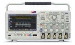
The Tektronix MSO2000B and DPO2000B Series is a family of mixed signal oscilloscopes that delivers advanced debug features at an entry-level price. The series offers up to 200 MHz of bandwidth and a 1 GS/s sample rate, with up to 20 channels available for analyzing analog and digital signals together. A deep record length of 1 Mpoint comes standard on all channels, letting you capture long windows of signal activity while maintaining fine timing resolution.
An oscilloscope captures voltage waveforms over time and displays them on screen, giving an engineer a direct view of a signal's amplitude, frequency, timing, and shape. This series is built to speed every stage of debugging a complex design — discovering an anomaly, capturing it, searching the waveform record for the event, and analyzing the device's behavior. Its tools target the infrequent problems common in digital systems, including runt pulses, glitches, and timing issues, and support troubleshooting of system-level interactions in complex embedded systems.
ValueTronics stocks and holds its own inventory in a 20,000 sq ft secure warehouse at 1675 Cambridge Drive in Elgin, Illinois, where we have specialized in new and used test and measurement equipment since 1992.
Tektronix was founded in 1946 in Oregon and built its reputation on oscilloscope technology. In 2007 it became a subsidiary of Danaher Corporation, and in 2016 it moved under Fortive Corporation following Fortive's spinoff from Danaher. The Tektronix brand itself has remained constant throughout.
The MSO2000B and DPO2000B Series groups twelve models on a common platform: a 1 GS/s sample rate on all channels, a 1 Mpoint record length on every channel, a 5,000 wfm/s maximum waveform capture rate, and Wave Inspector navigation and search. The DPO models are digital phosphor oscilloscopes, while the MSO models add 16 integrated digital channels for mixed-signal analysis.
Within that shared platform, the models step through three bandwidth tiers and two analog-channel counts, so a buyer can match bandwidth and channel requirements without changing instrument family or learning a different user interface.
Each new model below is its own dedicated product page with condition-matched pricing. Use the comparison table to identify the bandwidth, channel count, and MSO or DPO configuration you need, then open that model's page to see its current new availability.
The family separates along three axes. Bandwidth runs 70 MHz, 100 MHz, or 200 MHz, with corresponding rise-time specifications of 5 ns, 3.5 ns, and 2.1 ns. Analog channel count is either 2 or 4, with the model number's final digit indicating the channel count (a model ending in 2 is two-channel; ending in 4 is four-channel).
The MSO prefix designates models that add 16 digital channels to the corresponding DPO model; the DPO prefix designates the digital phosphor oscilloscope without those digital channels. Sample rate (1 GS/s), record length (1 Mpoint), and maximum waveform capture rate (5,000 wfm/s) are identical across every model. See the comparison table for the exact bandwidth, rise time, and channel configuration of each model.
| Model | Bandwidth | Analog Channels | Digital Channels |
|---|---|---|---|
| MSO2004B | 70 MHz | 4 | 16 |
| DPO2002B | 70 MHz | 2 | 0 |
| DPO2004B | 70 MHz | 4 | 0 |
| DPO2012B | 100 MHz | 2 | 0 |
Additional differences in specifications beyond the few shown above are not listed here — see each model's full specifications below.
| Specification | Value |
|---|---|
| Model Overview | |
| Analog channels | 2 (MSO/DPO2002B, 2012B, 2022B); 4 (MSO/DPO2004B, 2014B, 2024B) |
| Bandwidth | 70 MHz (MSO/DPO2002B, 2004B); 100 MHz (MSO/DPO2012B, 2014B); 200 MHz (MSO/DPO2022B, 2024B) |
| Rise time | 5 ns (70 MHz models); 3.5 ns (100 MHz models); 2.1 ns (200 MHz models) |
| Sample rate | 1 GS/s on all channels (all models) |
| Record length | 1 M points on all channels (all models) |
| Digital channels | MSO models add 16 digital channels to the corresponding DPO model |
| Vertical System, Analog Channels | |
| Hardware bandwidth limits | 20 MHz |
| Input coupling | AC, DC, GND |
| Input impedance | 1 MΩ ±2%, 11.5 pF ±2 pF |
| Input sensitivity range | 2 mV/div to 5 V/div |
| Vertical resolution | 8 bits |
| Maximum input voltage, 1 MΩ | 300 VRMS with peaks ≤ ±450 V |
| DC gain accuracy (with offset set to 0 V) | ±3% for 10 mV/div to 5 V/div; ±4% for 2 mV/div to 5 mV/div |
| Channel-to-channel isolation (any two channels at equal vertical scale) | ≥100:1 at ≤70 MHz (2002B/2004B); ≥100:1 at ≤100 MHz (2012B/2014B); 100:1 at ≤200 MHz (2022B/2024B) |
| Offset range, 1 MΩ input (2 mV/div to 200 mV/div) | ±1 V |
| Offset range, 1 MΩ input (>200 mV/div to 5 V/div) | ±25 V |
| Bandwidth at 2 mV/div | 20 MHz, all models |
| Vertical System, Digital Channels (MSO models) | |
| Input channels | 16 digital (D15 to D0) |
| Thresholds | Threshold per set of 8 channels |
| Threshold selections | TTL, CMOS, ECL, PECL, User-defined |
| User-defined threshold range | ±20 V |
| Threshold accuracy | ±[100 mV + 3% of threshold setting] |
| Maximum input voltage | ±40 V |
| Input dynamic range | 80 Vpk-pk (threshold setting dependent) |
| Minimum voltage swing | 500 mVp-p |
| Input resistance | 101 kΩ |
| Probe loading | 8 pF |
| Vertical resolution | 1 bit |
| Horizontal System, Analog Channels | |
| Maximum duration of time captured at highest sample rate (all channels) | 1 ms |
| Time base range | 200 MHz models: 2 ns to 100 s; 70, 100 MHz models: 4 ns to 100 s |
| Time-base delay time range | -10 divisions to 5000 s |
| Channel-to-channel deskew range | ±100 ns |
| Time base accuracy | ±25 ppm over any ≥1 ms interval |
| Horizontal System, Digital Channels (MSO models) | |
| Maximum sample rate (main), channels D7-D0 | 1 GS/s (1 ns resolution) |
| Maximum sample rate (main), channels D8-D15 | 500 MS/s (2 ns resolution) |
| Maximum record length (main, all channels) | 1 M points |
| Minimum detectible pulse width | 5 ns |
| Channel-to-channel skew | 2 ns typical |
| Trigger System | |
| Trigger modes | Auto, Normal, and Single |
| Trigger coupling | DC, HF reject (attenuates >85 kHz), LF reject (attenuates <65 kHz), noise reject (reduces sensitivity) |
| Trigger holdoff range | 20 ns to 8 s |
| Trigger sensitivity, typical — Internal DC coupled | 0.4 div from DC to 50 MHz; 0.6 div >50 MHz to 100 MHz; 0.8 div >100 MHz to 200 MHz |
| Trigger sensitivity, typical — External (aux input) | 200 mV from DC to 100 MHz, 1X attenuation |
| Trigger level range — Any input channel | ±4.92 divisions from center of screen |
| Trigger level range — Aux Input (external trigger) | ±6.25 V, 1X attenuation; ±12.5 V, 10X attenuation |
| Trigger types | Edge, Pulse Width, Runt, Logic, Setup and Hold, Rise/Fall Time, Video (NTSC, PAL, SECAM); optional serial: I2C (up to 3.4 Mb/s), SPI (up to 10.0 Mb/s), RS-232/422/485/UART (up to 10 Mb/s), CAN (up to 1 Mb/s), LIN; Parallel (MSO models only) |
| Acquisition System | |
| Sample | Acquire sampled values |
| Peak Detect | Captures glitches as narrow as 3.5 ns at all sweep speeds |
| Averaging | From 2 to 512 waveforms included in average |
| Roll | Scrolls waveforms right to left at sweep speeds slower than or equal to 40 ms/div |
| Waveform Measurements | |
| Cursors | Waveform and Screen |
| Automatic measurements | 29, of which up to four can be displayed on-screen at any one time |
| Gating | Isolate the specific occurrence within an acquisition using screen or waveform cursors |
| Waveform Math | |
| Arithmetic | Add, subtract, and multiply waveforms |
| FFT | Spectral magnitude. FFT Vertical Scale: Linear RMS or dBV RMS; FFT Window: Rectangular, Hamming, Hanning, or Blackman-Harris |
| Display System | |
| Display type | 7 inch (180 mm) wide format liquid crystal TFT color display |
| Display resolution | 480 horizontal × 234 vertical pixels (WQVGA) |
| Waveform styles | Vectors, Dots, Variable Persistence, Infinite Persistence |
| Graticules | Full, Grid, Cross Hair, Frame |
| Format | YT and XY |
| Maximum waveform capture rate | Up to 5,000 wfm/s |
Important: The optional 10/100 Ethernet (LAN) port and Video Out port require the DPO2CONN module.
Important: Serial protocol triggering and analysis (I2C, SPI, CAN, LIN, and RS-232/422/485/UART) is optional and requires the appropriate application module (DPO2AUTO, DPO2COMP, DPO2EMBD, or the DPO2BND bundle). It is offered free for a 30-day trial that starts automatically when the instrument is first powered on.
Important: Bandwidth is 20 MHz at 2 mV/div on all models.
Important: To use TekVPI active, differential, or current probes on the MSO/DPO2000B, the oscilloscope requires a TekVPI external power supply (119-7465-xx / 119-8726-xx), one per oscilloscope, plus an appropriate power cord for the country of use.
Important: On the DPO2EMBD module, only two-wire SPI support is available on two-channel models.
Important: Parallel bus triggering is available on MSO models only.
Important: The five-year warranty covers all parts and labor, excluding probes.
Recommended pairing: the TekVPI active, differential, and current probes in the recommended accessories list — such as the TAP1500, TDP0500, and TCP0030A — extend the series to high-voltage, differential, and current measurements.
This is a brand-new, factory-sealed unit, supplied exactly as it arrives from the manufacturer and backed by the full manufacturer warranty. For the exact configuration, available options, included accessories, or current lead time for your application, our Test Architects can confirm the details before you order.
ValueTronics supplies both new and used test and measurement equipment. New units ship factory-sealed, exactly as received from the manufacturer; every used unit is inspected and functionally verified in-house at our 20,000 sq ft secure facility in Elgin, Illinois before it ships. Our Test Architects can help you select the condition, calibration, and configuration that fit your application.
Please review the Manufacturer's Data Sheet to verify published specifications. Feedback on this webpage is always welcome — please reach out to your Test Architect at any time for questions or concerns. Thank you, we truly appreciate you being our customer.
Model No
Tektronix
Condition
Factory New
Manufacturer
Tektronix
Osc_ch
4
Osc_freq
70 MHz
Osc_r
1 MΩ
Osc_sampl
1 GS/s
TekBench
TekBench is instrument control software for DPO/MSO2000B Oscilloscopes

30+ Years in Business
Secure Payments
Sell Test Equipments
Knowledgeable Staff
On-site Lab
30+ Years in Business
Secure Payments
Sell Test Equipments
Knowledgeable Staff
On-site Lab
Request A Quote
 Chat Live
 Contact Us
 sales@valuetronics.com

