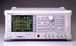
The Anritsu MS4630B is a network analyzer that operates from 10 Hz to 300 MHz, built for high-speed, accurate evaluation of IF filters, resonators, and similar devices on electronics production and inspection lines. It combines a high-speed synthesizer with digital signal processing to deliver fast, repeatable device measurements suited to production-throughput demands.
Its measurement work centers on the applications it was designed for: evaluating IF filter resonance and group delay characteristics, and measuring the impedance characteristics of resonators used in AV equipment and personal computers. Crystal resonators can be tested by combining the analyzer with a π-circuit jig such as the MA1506A, and filter pass/fail screening is performed in real time using the single and segmented limit-test functions.
ValueTronics keeps the MS4630B and the wider test-and-measurement catalog in stock at our own 20,000 square-foot secure warehouse at 1675 Cambridge Drive in Elgin, Illinois, where we hold and manage our inventory directly. Every used unit is inspected and functionally verified in-house before it ships, while new units leave the warehouse factory-sealed exactly as received.
| Specification | Value |
|---|---|
| Measurement items | |
| Transmission characteristics (ratio measurement) | Amplitude, phase, group delay |
| Reflection/impedance characteristics | Amplitude, phase (with external transducer) |
| Level characteristics | Absolute amplitude |
| Frequency | |
| Range | 10 Hz to 300 MHz |
| Resolution | 0.01 Hz |
| Accuracy (standard): Aging rate | ≤1 x 10⁻⁶/day (15 minutes after power-on) |
| Accuracy (standard): Temperature characteristics | ≤±5 x 10⁻⁶ (0° to +50°C) |
| Accuracy (Option 13: High-stability reference oscillator): Aging rate | ≤±2 x 10⁻⁸/day (24 h after power-on) |
| Accuracy (Option 13): Temperature characteristics | ≤±5 x 10⁻⁸ (0° to +50°C) |
| Input | |
| Channel No. | Standard: 2 (R, TA); Option 12: 3 (R, TA, TB) |
| Impedance | 50 Ω, 1 MΩ switchable (when combined with MA4605A: 75 Ω, 1 MΩ) |
| Input range (IRG) | 0/+20 dBm |
| Max. input power | AC: +20 dBm; DC ±2.2 V (50 Ω); AC: 0 dBm; DC: ±20 V (1 MΩ) |
| Connector | BNC-J |
| Probe source | +12 ±1 V, 100 mA (with protective circuit for shorts) |
| Average noise level | ≤–120 dBm (RBW: 1 kHz, 1 to 300 MHz), ≤–110 dBm (RBW: 1 kHz, 80 kHz to 1 MHz) |
| Crosstalk (between channels) | ≥120 dB (80 kHz to 300 MHz), ≥110 dB (up to 80 kHz) |
| Crosstalk (between transmitter and receiver) | ≥125 dB |
| Resolution bandwidth | 3, 10, 30, 100, 500 Hz, 1, 2, 3, 4, 5, 10, 20 kHz and automatic setting |
| Output | |
| Output level range (Output A) | 0 to +21 dBm; Option 10: –70 to +21 dBm |
| Output level range (Output B) | –6 to +15 dBm (–9.5 to +11.5 dB when Option 14 added); Option 10: –76 to +15 dBm (–79.5 to +11.5 dB when Option 14 added) |
| Output resolution | 0.01 dB |
| Output level accuracy | ≤±1.0 dB (frequency: 100 MHz, Output A: +10 dBm) |
| Output level linearity | ≤±0.5 dB (0 dBm reference, frequency: 100 MHz, Output A: 0 to +21 dBm) |
| Output level deviation | ≤±1.5 dB (output A: +10 dBm, 100 MHz reference) |
| Step error | ±0.5 dB (Option 10) |
| Output impedance | 50 Ω (when combined with MA4605A: 75 Ω) |
| Connector | BNC-J |
| Amplitude measurement | |
| Measurement range | ≥120 dB |
| Measurement resolution | 0.001 dB |
| Display scale | 0.01 dB/div to 50 dB/div (1-2-5 sequence) |
| Dynamic accuracy, Amplitude (80 kHz to 100 MHz / 10 kHz to 300 MHz) | |
| 0 to –10 dB | ±0.20 dB / ±0.20 dB |
| –10 to –60 dB | ±0.05 dB / ±0.05 dB |
| –60 to –70 dB | ±0.10 dB / ±0.30 dB |
| –70 to –80 dB | ±0.30 dB / ±1.00 dB |
| –80 to –90 dB | ±1.20 dB / ±4.00 dB |
| –90 to –100 dB | ±4.00 dB / – |
| Phase measurement | |
| Measurement range | ±180° |
| Measurement resolution | 0.001° |
| Display scale | 0.01° to 50°/div (1-2-5 sequence) |
| Dynamic accuracy, Phase (80 kHz to 100 MHz / 10 kHz to 300 MHz) | |
| 0 to –10 dB | ±1.5° / ±1.5° |
| –10 to –60 dB | ±0.3° / ±0.3° |
| –60 to –70 dB | ±0.8° / ±2.0° |
| –70 to –80 dB | ±2.0° / ±6.0° |
| –80 to –90 dB | ±6.0° / ±20.0° |
| –90 to –100 dB | ±20.0° / – |
| Group delay measurement | |
| DRG | ∆θ/(360 x ∆F) |
| Measurement resolution | 2.78 x 10⁻⁵/∆F |
| Display scale | 1 ps/div to 50 ms/div |
| Dynamic accuracy | Phase measurement accuracy/(360 x aperture frequency) |
| Calibration, correction | |
| Calibration types | Frequency response, 1 port, 1 path-2 port, frequency response/isolation calibration, π-NET calibration |
| Calibration data interpolation | Measurement frequency; when number of measurement points changed, new calibration data interpolation calculation based on calibration data before change (except at log frequency measurement and 1001 measurement points) |
| Normalize | X–S |
| Electrical length calibration range | 0 to ±999999.9999999 m, Resolution: 100 nm |
| Phase offset range | ±180° |
| Sweeping | |
| Frequency sweep | LIN (CENTER/SPAN, START/STOP), LOG (START/STOP) |
| Level sweep | LIN (START/STOP/STEP) |
| List sweep | Frequency, level, RBW, the individual setting in the waiting time |
| Number of measurement points | 11, 21, 51, 101, 251, 501, 1001 |
| Break point | Anywhere between 1 and 1001 |
| Sweep time | 150 µs/point, 38 ms/250 points full sweep (RBW: 20 kHz, normalize calibration, 1 trace) |
| Setting range | 1 ms to 27.5 h |
| Sweep range | Full sweep, part sweep (between markers) |
| Sweep control | REPEAT/SINGLE, STOP/CONT |
| Sweep trigger | INT/EXT (RISE, FALL, LEVEL) |
| Display | |
| Max. display screens | 2 channels, 4 traces |
| Display format | LOG MAG (M), PHASE (P), DELAY (D), M/P, M/D, LIN MAG (LIN), LIN/P, LIN/D, REAL (R), IMAG (I), R/I, Z, Z/θ, Q, Z/Q, POLAR, VSWR, IMPD (Z∠θ, Rs + Ls/Cs, Q/D, R + jx), ADMT (Y∠θ, Rp + Lp/Cp, Q/D, G + jB) |
| Display | 640 x 480 dots, 16.5 cm color LCD |
| Markers | |
| Marker functions | NORMAL MKR, ∆MKR, 0 MKR, MKR →MAX, MKR →MIN, MKR →CF, ∆→SPAN, MKR →+PEAK, MKR →–PEAK, MKR TRACK + PEAK, MKR TRACK–PEAK, MKR CHANGE, MKR OFFSET |
| Setting | Set marker position to frequency or point |
| Multi-marker | Max. 10 markers for each trace |
| Measurement parameters | |
| Filter function | F0, IL, passband (L, R), attenuation band (L, R), Ripple, Q, SF |
| Resonator function RESON 1 | Fr, Fa, Zr, Za (0 PHASE), Fm, Fn, Zm, Zn (MAX/MIN) |
| Resonator function RESON 2 | Fs, Fr, Fa, Zr, Za, Q, equivalence constant (R1, L1, C1, C0) |
| Averaging functions | Method: SUM, MAX, MIN; Count: 1 to 1000 |
| Main trace (MT) memory | 2 each (XMEM) for Channel 1 and Channel 2 |
| Calibration S memory | 2 each (SMEM) for Channel 1 and Channel 2 |
| Image memory | 2 each (IMEM) for Channel 1 and Channel 2 |
| Sub-trace (ST) | MT →ST, MT = MT–ST, MT = ST |
| Limit line | Single or segment (10) limit line, pass/fail evaluation against limit line |
| Receive bandwidth and sweep time auto-setting | Receive bandwidth set automatically for set sweep time; automatically set to give minimum sweep time at set receive bandwidth |
| Function memory / Auxiliary media | |
| Saving/recalling data | Measurement parameters, measured data, calibration data, PTA application programs saved/recalled to/from FD, PMC and Internet memory |
| FD | 100 functions max. |
Important: Maximum input power: AC +20 dBm / DC ±2.2 V (50 Ω); AC 0 dBm / DC ±20 V (1 MΩ).
Important: Reflection and impedance characteristic measurements require an external transducer (e.g., a reflection bridge or impedance probe), which is not supplied with the main frame and must be ordered separately (see Optional accessories).
Important: Crystal resonators are tested by combining the MS4630B with a π-circuit jig such as the MA1506A; the floating admittance around the jig is eliminated using the MS4630B π-network calibration function and the jig calibration standard.
This pre-owned unit is inspected and functionally verified in-house before it ships and is backed by our pre-owned warranty. To confirm its exact condition, firmware revision, installed options, or included accessories for your application before ordering, contact our Test Architects.
ValueTronics supplies both new and used test and measurement equipment. New units ship factory-sealed, exactly as received from the manufacturer; every used unit is inspected and functionally verified in-house at our 20,000 sq ft secure facility in Elgin, Illinois before it ships. Our Test Architects can help you select the condition, calibration, and configuration that fit your application.
Please review the Manufacturer's Data Sheet to verify published specifications. Feedback on this webpage is always welcome — please reach out to your Test Architect at any time for questions or concerns. Thank you, we truly appreciate you being our customer.
Model No
Anritsu
Condition
Pre-Owned
Manufacturer
Anritsu
Net_ana_freq
10 Hz to 300 MHz
10
70 dB Mechanical Output Attenuator

30+ Years in Business
Secure Payments
Sell Test Equipments
Knowledgeable Staff
On-site Lab
30+ Years in Business
Secure Payments
Sell Test Equipments
Knowledgeable Staff
On-site Lab
Request A Quote
 Chat Live
 Contact Us
 sales@valuetronics.com