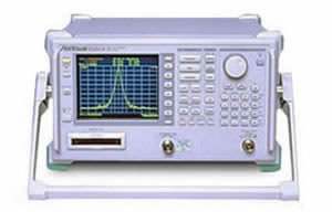
The Anritsu MS2661C is a portable synthesized spectrum analyzer covering 9 kHz to 3 GHz, designed for signal analysis of radio and other equipment related to improving frequency usage efficiency, higher modulation, and digitalization. The instrument combines high C/N ratio, low distortion, and high frequency and level accuracy in a portable package suitable for both field and bench use.
Per the datasheet, the MS2661C addresses analysis of digital radio equipment and CATV signals. The built-in Measure function supports evaluation of radio equipment through dedicated routines for frequency counter, C/N, adjacent channel power, occupied frequency bandwidth, burst average power, and template decision functions. A two-screen display capability and FM demodulation waveform display extend the instrument's application reach within these areas.
Anritsu Corporation is a Japanese precision measurement company with roots stretching to 1895. The Anritsu organization relevant to the test and measurement market was significantly shaped by its 1993 acquisition of Wiltron Company, which transferred Wiltron's RF and microwave measurement technology and North American commercial presence into Anritsu. Instruments originally branded Wiltron are part of the Anritsu product lineage today.
| Frequency | |
|---|---|
| Frequency range | 9 kHz to 3 GHz |
| Display frequency accuracy | ± (display frequency x reference frequency accuracy + span x span accuracy + 100 Hz) *Span: ≥10 kHz, after calibration |
| Marker frequency display accuracy | Normal: Same as display frequency accuracy; Delta: Same as frequency span accuracy |
| Frequency counter | Resolution: 1 Hz, 10 Hz, 100 Hz, 1 kHz; Accuracy: Display frequency x reference frequency accuracy ±1 LSD (at S/N: ≥20 dB) |
| Frequency span | Setting range: 0 Hz, 1 kHz to 3.1 GHz; Accuracy: ±2.5% (span: ≥10 kHz), ±5% (span: <10 kHz, with option 02) |
| Resolution bandwidth (RBW) (3 dB bandwidth) | Setting range: 1 kHz, 3 kHz, 10 kHz, 30 kHz, 100 kHz, 300 kHz, 1 MHz, 3 MHz (manually settable, or automatically settable according to frequency span). *Option 02: 30 Hz, 100 Hz, and 300 Hz are added. Bandwidth accuracy: ±20% (1 kHz to 1 MHz), ±30% (3 MHz). Selectivity (60 dB : 3 dB): ≤15:1 |
| Video bandwidth (VBW) | 1 Hz to 3 MHz (1-3 sequence), OFF (manually settable, or automatically settable according to RBW) |
| Noise sideband, stability | Noise sideband: ≤–100 dBc/Hz (1 GHz, 10 kHz offset); Residual FM: ≤20 Hzp-p/0.1 s (1 GHz, span: 0 Hz); Frequency drift: ≤200 Hz/min (span: ≤10 kHz, sweep time: ≤100 s) *After 1-hour warm-up at constant ambient temperature |
| Reference oscillator | Frequency: 10 MHz; Aging rate: 2 x 10⁻⁶/year (typical); Option 01: 1 x 10⁻⁷/year, 2 x 10⁻⁸/day; Temperature characteristics: 1 x 10⁻⁵ (typical, 0° to 50°C); Option 01: ±5 x 10⁻⁸ (0° to 50°C) *Referenced to frequency at 25°C |
| Amplitude | |
| Level measurement | Measurement range: Average noise level to +30 dBm; Maximum input level: +30 dBm (CW average power, RF ATT: ≥10 dB), ±50 Vdc; Average noise level: ≤–115 dBm (1 MHz to 1 GHz), ≤–115 dBm + f [GHz] dB (>1 GHz), ≤–114 dBm (1 MHz to 1 GHz, at Option 08 pre-amplifier installed), ≤–114 dBm + 1.5f [GHz] dB (>1 GHz, at Option 08 pre-amplifier installed) *RBW: 1 kHz, VBW: 1 Hz, RF ATT: 0 dB; Residual response: ≤–100 dBm (RF ATT: 0 dB, input: 50 Ω termination, 1 MHz to 3 GHz) |
| Total level accuracy | ±1.3 dB (100 kHz to 3 GHz) *Level measurement accuracy after calibration using internal calibration signal. Total level accuracy: Reference level accuracy (0 to –49.9 dBm) + frequency response + log linearity (0 to –20 dB) + calibration signal source accuracy |
| Reference level | Setting range: Log scale: –100 to +30 dBm; Linear scale: 224 µV to 7.07 V. Unit: Log scale: dBm, dBµV, dBmV, V, dBµVemf, W, dBµV/m; Linear scale: V. Reference level accuracy: ±0.4 dB (–49.9 to 0 dBm), ±0.75 dB (–69.9 to –50 dBm, 0.1 to +30 dBm), ±1.5 dB (–80 to –70 dBm) *After calibration, at 100 MHz, span: 1 MHz (when RF ATT, RBW, VBW, and sweep time set to AUTO). RBW switching uncertainty: ±0.3 dB (1 kHz to 1 MHz), ±0.4 dB (3 MHz) *After calibration, referenced to RBW: 3 kHz. Input attenuator (RF ATT): Setting range: 0 to 70 dB (10 dB steps) *Manually settable, or automatically settable according to reference level; Switching uncertainty: ±0.3 dB (0 to 50 dB), ±1.0 dB (0 to 70 dB) *After calibration, frequency: 100 MHz, referenced to RF ATT: 10 dB |
| Frequency response | ±0.5 dB (100 kHz to 3 GHz, referenced to 100 MHz, RF ATT: 10 dB, 18° to 28°C); ±1.5 dB (9 to 100 kHz, referenced to 100 MHz, RF ATT: 10 dB, 18° to 28°C); ±1.0 dB (100 kHz to 3 GHz, referenced to 100 MHz, RF ATT: 10 to 50 dB) |
| Waveform display | Scale (10 div): Log scale: 10, 5, 2, 1 dB/div; Linear scale: 10, 5, 2, 1%/div. Linearity (after calibration): Log scale: ±0.4 dB (0 to –20 dB), ±1.0 dB (0 to –70 dB), ±1.5 dB (0 to –85 dB), ±2.5 dB (0 to –90 dB); Linear scale: ±4% (compared to reference level). Marker level resolution: Log scale: 0.01 dB; Linear scale: 0.02% of reference level |
| Spurious response | 2nd harmonic distortion: ≤–60 dBc (10 to 200 MHz), ≤–75 dBc (0.2 to 1.5 GHz), ≤–80 dBc (0.8 to 1 GHz) *Mixer input: –30 dBm. Two signals 3rd order intermodulation distortion: ≤–70 dBc (10 to 100 MHz), ≤–80 dBc (0.1 to 3 GHz) *Frequency difference of two signals: ≥50 kHz, mixer input: –30 dBm |
| 1 dB gain compression | ≥–5 dBm (≥100 MHz, at mixer input level) |
| Maximum dynamic range | 1 dB gain compression level to average noise level: >110 dB (0.1 to 1 GHz), >110 dB – f [GHz] dB (>1 GHz), >109 dB (0.1 to 1 GHz, at Option 08 pre-amplifier installed), >109 dB – 1.5f [GHz] (>1 GHz, at Option 08 pre-amplifier installed). Distortion characteristics (RBW: 1 kHz): 2nd harmonic: >72.5 dB (10 to 200 MHz), >80 dB (200 to 500 MHz), >80 – f [GHz] dB (0.5 to 1.5 GHz), >82.5 – f [GHz] dB (0.8 to 1 GHz); 3rd order intermodulation: >80 dB (10 to 100 MHz), >83.3 dB (0.1 to 1 GHz), >83.3 – (2/3)f [GHz] dB (1 to 3 GHz) |
| Sweep | |
| Sweep time | Setting range: 20 ms to 1000 s (Manually settable, or automatically settable according to span, RBW and VBW); Accuracy: ±15% (20 ms to 100 s), ±45% (110 to 1000 s), ±1% (time domain sweep: digital zero span mode) |
| Sweep mode | Continuous, single |
| Time domain sweep mode | Analog zero span, digital zero span |
| Zone sweep | Sweeps only in frequency range indicated by zone marker |
| Tracking sweep | Sweeps while tracing peak points within zone marker (zone sweep also possible) |
| Functions | |
| Number of data points | 501 |
| Detection mode | NORMAL, POS PEAK, NEG PEAK, SAMPLE; Detection mode switching uncertainty: ±0.5 dB (at reference level) |
| Display | Color TFT-LCD, Size: 5.5 inch, Number of colors: 17 (RGB, each 64-scale settable); Intensity adjustment: 5 steps settable |
| Display functions | Trace A: Displays frequency spectrum; Trace B: Displays frequency spectrum; Trace Time: Displays time domain waveform at center frequency; Trace A/B; Trace A/BG; Trace A/Time; Trace move/calculation: A → B, B → A, A ↔ B, A + B → A, A – B → A, A – B + DL → A |
| Storage functions | NORMAL, VIEW, MAX HOLD, MIN HOLD, AVERAGE, CUMULATIVE, OVER WRITE |
| FM demodulation waveform display function | Demodulation range: 2, 5, 10, 20, 50, 100, 200 kHz/div; Marker display accuracy: ±5% of full scale (when referenced to center frequency, DC-coupled, RBW: 3 MHz, VBW: 1 Hz, CW) |
| Input connector | N-J, 50 Ω |
| Auxiliary signal input and output | IF OUTPUT: 10.69 MHz, BNC connector; VIDEO OUTPUT (Y): 0 to 0.5 V ±0.1 V (100 MHz, from lower edge to upper edge at 10 dB/div or 10%/div, 75 Ω terminated, BNC connector); COMPOSITE OUTPUT: For NTSC, 1 Vp-p (75 Ω terminated), BNC connector; EXT REF INPUT: 10 MHz ±10 Hz, ≥0 dBm (50 Ω terminated), BNC connector |
| Signal search | AUTO TUNE, PEAK → CF, PEAK → REF, SCROLL |
| Zone marker | NORMAL, DELTA |
| Marker → | MARKER → CF, MARKER → REF, MARKER → CF STEP SIZE, ΔMARKER → SPAN, ZONE → SPAN |
| Peak search | PEAK, NEXT PEAK, NEXT RIGHT PEAK, NEXT LEFT PEAK, MIN DIP, NEXT DIP |
| Multimarker | Number of markers: 10 max. (HIGHEST 10, HARMONICS, MANUAL SET) |
| Measure | Noise power (dBm/Hz, dBm/ch), C/N (dBc/Hz, dBc/ch), occupied bandwidth (power N% method, X-dB down method), adjacent channel power (REF: total power/reference level/in-band level method, channel designate display: 2 channels x 2 graphic display), average power of burst signal (average power in designated time range of time domain waveform), channel power (dBm, dBm/Hz), template comparison (upper/lower limits x each 2, time domain), MASK (upper/lower x each 2, frequency domain) |
| Save/recall | Saves and recalls setting conditions and waveform data to internal memory (max. 12) or memory card |
| Hard copy | Printer (HP dotmatrix, EPSON dotmatrix or compatible models): Display data can be hard-copied via RS-232C, GPIB, and Centronics (Option 10) interface; Plotter (HP-GL, GP-GL compatible models): Display can be output via RS-232C and GPIB interface |
| PTA | Language: PTL (interpreter based on BASIC); Programming: Using editor of external computer; Program memory: Memory card, upload/download to/from external computer; Programming capacity: 192 KB; Data processing: Directly accesses measurement data according to system variables, system subroutines, and system functions |
| RS-232C | Outputs data to printer and plotter. Control from external computer (excluding power switch) |
| GPIB | Meets IEEE488.2. Controlled by external computer (excluding power switch). Or controls external equipment with PTA. Interface function: SH1, AH1, T6, L4, SR1, RL1, PP0, DC1, DT1, C1, C2, C3, C4, C28 |
| Correction | Automatic correction of insertion loss of MA1621A Impedance Transformer; Correction accuracy (RF ATT: ≥10 dB): ±2.5 dB (9 to 100 kHz), ±1.5 dB (100 kHz to 2 GHz), ±2.0 dB (2 to 3 GHz) *Typical value. Antenna correction coefficients: Correct display and measurement of field strengths (dBµV/m) for specified antennas, Internal antenna correction coefficients (MP534A/651A Dipole Antenna, MP635A/666A Log-Periodic Antenna, MP414B Loop Antenna, and four antennas user-defined; writes via GPIB or RS-232C interface, saves/loads to/from memory card) |
| Memory card interface | Functions: Saving/recalling measurement parameters/waveform data, uploading/downloading PTA programs; Applicable cards: SRAM, EPROM, Flash EPROM *Only SRAM writable; Card capacity: 2 MB max. Connector: Meets the PCMCIA Rel. 2.0, 2 slots |
| Others | |
| EMC | EN61326: 1997/A1, 1998 (Class A); EN61000-3-2: 1995/A2, 1998 (Class A); EN61326: 1997/A1, 1998 (Annex A) |
| LVD | EN61010-1: 1993/A2, 1995 (Installation Category II, Pollution degree 2) |
| Vibration | Meets the MIL-STD-810D |
| Power (operating range) | 85 to 132/170 to 250 Vac (automatic voltage switching), 47.5 to 63 Hz, 380 to 420 Hz (85 to 132 V only), ≤330 VA |
| Dimensions and mass | 320 (W) x 177 (H) x 351 (D) mm, ≤10.8 kg (without option) |
| Ambient temperature | 0° to +50°C (operate), –40° to +75°C (storage) |
Please review the Manufacturer's Data Sheet to verify published specifications. Feedback on this webpage is always welcome — please reach out to your Test Architect at any time for questions or concerns. Thank you, we truly appreciate you being our customer.
Model No
Anritsu
Condition
Used
Manufacturer
Anritsu
Frequency
3 GHz
1
Reference Crystal Oscillator
2
Narrow resolution bandwidths
8
Pre-amplifier

30+ Years in Business
Secure Payments
Sell Test Equipments
Knowledgeable Staff
On-site Lab
30+ Years in Business
Secure Payments
Sell Test Equipments
Knowledgeable Staff
On-site Lab
Request A Quote
 Chat Live
 Contact Us
 sales@valuetronics.com