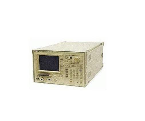
The Anritsu MS2601A is a wide-band spectrum analyzer covering 10 kHz to 2.2 GHz across the video, VHF, and UHF bands. The synthesized local oscillator and automatic calibration enable accurate frequency and level measurement, while features such as the zone marker and scroll function shorten measurement time. Plug-in Memory Cards (PMCs) provide storage for measurement conditions and waveform data, supporting repeatable test setups. The MS2601J is the 75-ohm input variant of the same platform.
A spectrum analyzer displays signal energy across a frequency range — showing what signals are present, at what frequency, and at what power level. This is the frequency-domain view that complements the time-domain view of an oscilloscope and is the standard instrument for characterizing RF transmitters, identifying interference, and measuring electromagnetic emissions.
ValueTronics has supplied new and pre-owned test and measurement instruments since 1992 from our 20,000 square foot secure warehouse at 1675 Cambridge Drive in Elgin, Illinois. Every spectrum analyzer that passes through our facility is inspected and performance-tested in-house by our technicians before it ships, which is why our condition descriptions reflect measured performance rather than seller assumption. We hold one of the deepest inventories of legacy Anritsu instruments in North America and we maintain a working knowledge of the platforms — including the MS2601A/J — that remain active in production test, EMC pre-compliance, and RF maintenance environments today.
Anritsu is a Japanese precision measurement company with roots dating to 1895. In 1993 Anritsu acquired Wiltron Company, the US-based RF and microwave instrument manufacturer, consolidating two long-established RF measurement brands under the Anritsu name. Instruments originally branded Wiltron are part of the Anritsu product lineage and are supported through current Anritsu channels.
The MS2601 family from Anritsu consists of two variants of the same wide-band spectrum analyzer platform covering 10 kHz to 2.2 GHz. According to the datasheet, the MS2601A and MS2601J are functionally identical apart from RF input impedance and the resulting differences in frequency response specifications and connector type.
Both variants share the same synthesized local oscillator architecture, the same high-level built-in automatic calibration that delivers approximately 1 dB general level measurement accuracy, the same zone marker and scroll functions, the same QP detector and CISPR-conformant resolution bandwidths for EMI work, and the same PMC and optional PTA automation framework. The choice between the two models is determined by the system impedance of the device under test.
Each pre-owned MS2601 variant linked below is its own product page with condition-matched pricing. Select the page that matches the impedance variant — MS2601A for 50 Ω systems or MS2601J for 75 Ω systems — and the condition grade appropriate to your application.
On the MS2601A specifically, the RF input is 50 Ω with VSWR ≤1.5 at input attenuator ≥10 dB and frequency ≥30 kHz, using an N-type connector. The frequency response is specified at ±0.5 dB from 100 kHz to 2.0 GHz with input attenuator at 20 dB across the 20°C to 30°C temperature range, and 2nd and 3rd harmonic distortion is specified at ≤-75 dB for 5 to 800 MHz with 0 dB input attenuator and -30 dBm input level.
The MS2601A and MS2601J differ in RF input impedance, the resulting VSWR specification, the input connector type, and the upper frequency limit of the frequency response specification. The MS2601A presents 50 Ω with an N-type connector and is specified for ±0.5 dB frequency response to 2.0 GHz. The MS2601J presents 75 Ω with an NC-type connector and is specified for ±0.5 dB frequency response to 1.5 GHz.
Average noise level also differs between the variants. On the MS2601A the datasheet specifies ≤-120 dBm at 1 MHz to 2 GHz with 0 dB input attenuator, 300 Hz resolution bandwidth, and 1 Hz video bandwidth. On the MS2601J the same conditions yield ≤-114 dBm. Residual response is specified at ≤-100 dBm on the MS2601A with 50 Ω termination and ≤-95 dBm on the MS2601J with 75 Ω termination.
| Model | Frequency Range | RF Input Impedance | RF Connector |
|---|---|---|---|
| MS2601J | 9 kHz to 2.2 GHz | 75 Ω | NC-type |
| MS2601A | 9 kHz to 2.2 GHz | 50 Ω | N-type |
Additional differences in specifications beyond the few shown above are not listed here — see each model's full specifications below.
| Specification | MS2601A | MS2601J |
|---|---|---|
| Frequency | ||
| Measurement frequency range | 9 kHz to 2.2 GHz | |
| Readout modes | Center-span, start-span | |
| Center frequency/start frequency — Setting range | 0 to 2210 MHz (readout resolution 20 Hz) | |
| Center frequency/start frequency — Readout accuracy | ±(100 Hz + 2% of frequency span + tuning frequency × reference frequency accuracy) at frequency span ≥ 10 kHz, after automatic calibration | |
| Frequency span — Setting range | 1 kHz to 2200 MHz for horizontal 10 divisions, 2-digit (10 to 98) variable, and 0 Hz (fixed tuning); 1 kHz to 2000 MHz; 1-2-5 sequence at step keys | |
| Frequency span — Readout accuracy | ±2% | |
| Resolution bandwidth | 30 Hz to 1 MHz (3 dB bandwidth), variable in 1-3 sequence, can be selected manually or automatically coupled to frequency span | |
| Resolution bandwidth accuracy | ±20% | |
| Selectivity | ≤ 15 : 1 (ratio of 60 dB and 3 dB bandwidth) | |
| Residual FM | ≤ 20 Hz p-p/0.1 s (frequency span ≤ 500 kHz) | |
| Drift | ≤ 300 Hz/min (frequency span ≤ 500 kHz, after 1-hour warm-up at constant ambient temperature) | |
| Sideband noise | ≤ -80 dBc (at 100 Hz resolution bandwidth, 1 Hz video bandwidth, 10 kHz from signal) | |
| Reference oscillator frequency | 10 MHz | |
| Reference oscillator — Starting characteristic | ≤ 5 × 10⁻⁸ (after 20-minute warm-up, referred to frequency after 1-hour warm-up) | |
| Reference oscillator — Aging rate | ≤ 2 × 10⁻⁸/day, ≤ 1 × 10⁻⁷/year (referred to frequency after 24-hour warm-up) | |
| Reference oscillator — Temperature characteristic | ≤ 5 × 10⁻⁸ (referred to frequency at 25°C) | |
| External reference input | Frequency: 10 MHz; level: 2 to 5 Vp-p | |
| NORMAL marker — Function | Displays frequency at tunable marker | |
| NORMAL marker — Readout accuracy | Same as center frequency | |
| Δ(delta) marker — Function | Displays frequency difference between reference marker and tunable marker | |
| Δ(delta) marker — Readout accuracy | Same as frequency span accuracy | |
| COUNT marker — Function | Displays received signal frequency at marker | |
| COUNT marker — Resolution | 1 Hz, 10 Hz, 100 Hz selectable | |
| COUNT marker — Readout accuracy | Tuning frequency × reference frequency accuracy ±(2 counts or 20 Hz, whichever is greater) | |
| Amplitude | ||
| Measurement range | -130 to +20 dBm | -124 to +20 dBm |
| Display divisions | 8 divisions on vertical axis when top line is reference level and scale is 10 dB/div; 10 divisions on vertical axis for other scales | |
| Display — LOG 10 dB/div | 0 to -70 dB, referred to reference level | |
| Display — LOG 5 dB/div | 0 to -50 dB, referred to reference level | |
| Display — LOG 2 dB/div | 0 to -20 dB, referred to reference level | |
| Display — LOG 1 dB/div | 0 to -10 dB, referred to reference level | |
| Display — LIN | 10%/div of reference level (calibrated in voltage; unit: V) | |
| Linearity | LOG: ±0.2 dB/0 to -10 dB, ±0.3 dB/0 to -20 dB, ±0.5 dB/0 to -50 dB (resolution bandwidth of 100 Hz to 1 MHz), ±1 dB/0 to -70 dB (resolution bandwidth of 100 Hz to 100 kHz), after automatic calibration. LIN: ±3% of reference level (fullscale). | |
| Frequency response | ±0.5 dB (100 kHz to 2.0 GHz), input ATT at 20 dB, temperature range 20° to 30°C | ±0.5 dB (100 kHz to 1.5 GHz), input ATT at 20 dB, temperature range 20° to 30°C |
| Reference level — LOG setting range | +20 to -100 dBm (setting resolution 0.1 dB) | +20 to -100 dBm (setting resolution 0.1 dB) |
| Reference level — LIN setting range | 2240 mV to 70.8 µV | 2750 mV to 87.1 µV |
| Reference level accuracy | ±0.3 dB (0 to -50 dBm), ±0.75 dB (+20 to -70 dBm) after automatic calibration at frequency of 50 MHz and frequency span ≤ 2 MHz (resolution bandwidth, video bandwidth, sweep time, and input ATT settings at AUTO) | |
| Resolution bandwidth switching deviation | ±0.3 dB (after automatic calibration) | |
| Average noise level | ≤ -120 dBm (frequency 1 MHz to 2 GHz) with 0 dB input ATT, 300 Hz resolution bandwidth, 1 Hz video bandwidth | ≤ -114 dBm (frequency 1 MHz to 2 GHz) with 0 dB input ATT, 300 Hz resolution bandwidth, 1 Hz video bandwidth |
| 2nd and 3rd harmonic distortion | ≤ -75 dB (frequency 5 to 800 MHz) when 0 dB input ATT and -30 dBm input level | |
| Residual response | ≤ -100 dBm (frequency ≥ 500 kHz) when 0 dB input ATT and 50 Ω input termination | ≤ -95 dBm (frequency ≥ 500 kHz) when 0 dB input ATT and 75 Ω input termination |
| Marker NORMAL | Displays level at tunable marker | |
| Marker Δ(delta) | Displays level difference between tunable marker and reference marker | |
| Video bandwidth | 1 Hz, 10 Hz, 100 Hz, 1 kHz, 10 kHz, 100 kHz, OFF (selected manually or automatically coupled to resolution bandwidth) | |
| Level unit | dBm, dBµV, dBmV, V, dBµV (emf), dBµV/m | |
| QP detection | The charge, discharge, and display time constants conforming to CISPR standards are provided at 200 Hz, 9 kHz, and 120 kHz resolution bandwidth | |
| RF input impedance | 50 Ω VSWR ≤ 1.5 (input ATT ≥ 10 dB, frequency ≥ 30 kHz), N-type connector | 75 Ω VSWR ≤ 1.5 (input ATT ≥ 10 dB, frequency 30 kHz to 2 GHz), NC-type connector |
| Maximum input level | +25 dBm (input ATT ≥ 10 dB), DC: ±50 V | |
| Input ATT — Attenuation | 0 to 50 dB, in 10 dB steps (selected manually or automatically coupled to reference level) | |
| Input ATT — Switching accuracy | ±1 dB (100 kHz to 1.5 GHz), ±2.0 dB (1.5 to 2 GHz) | |
| Sweep | ||
| Sweep time | 50 ms to 100 s variable in 1, 1.5, 2, 3, 5, 7 sequence. Selected manually or automatically coupled to frequency span, resolution bandwidth, and video bandwidth. | |
| Trigger | FREE RUN, LINE, VIDEO, SINGLE, EXT TRIGGER | |
| Sweep range | Normal: sweeps entire range. Zone sweep: sweeps range between zone markers. | |
| CRT Display | ||
| CRT | Six-inch electromagnetic deflection type (amber display color) | |
| Display items | Graticule (grid), waveform data, setting conditions, menu, title | |
| Waveform data display method | Digital storage, two channels (A and B), horizontal axis: 501 points | |
| Other | ||
| Direct plotting | Screen data hard-copied to X-Y plotter or dot-matrix printer (compatible models only) via GP-IB |
Please review the Manufacturer's Data Sheet to verify published specifications. Feedback on this webpage is always welcome — please reach out to your Test Architect at any time for questions or concerns. Thank you, we truly appreciate you being our customer.
Model No
Anritsu
Condition
Used
Manufacturer
Anritsu
Frequency
2.2 GHz

30+ Years in Business
Secure Payments
Sell Test Equipments
Knowledgeable Staff
On-site Lab
30+ Years in Business
Secure Payments
Sell Test Equipments
Knowledgeable Staff
On-site Lab
Request A Quote
 Chat Live
 Contact Us
 sales@valuetronics.com