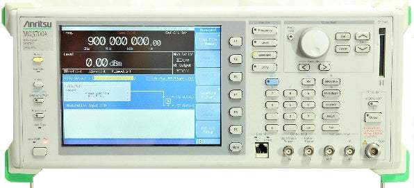
The Anritsu MG3700A is a vector signal generator built around a 160-MHz arbitrary waveform generator, combining a wide vector modulation bandwidth with large-capacity baseband memory. It generates digital modulation signals across a broad range of wireless systems, supporting evaluation of general-purpose mobile communications such as mobile phones as well as wireless LANs.
A vector signal generator produces controllable, modulated RF stimulus signals used to exercise a device under test so its response can be measured. The MG3700A is applied to evaluating receiver characteristics of base stations and UEs across various mobile communications systems, to testing multi-mode wireless devices that support several technologies at once, and to research and development of evolving communication systems. Its waveform combining function lets a single unit output a wanted signal together with an interfering signal or with AWGN for measurements such as Adjacent Channel Selectivity (ACS) and blocking characteristics.
ValueTronics International stocks and holds its own inventory in a 20,000 sq ft secure warehouse at 1675 Cambridge Drive in Elgin, Illinois. Every pre-owned unit we sell is inspected and functionally verified in-house by our technicians before it ships, while new units ship factory-sealed exactly as received from the manufacturer, so you can buy with confidence whichever condition fits your budget and application.
| Specification | Value |
|---|---|
| Frequency | |
| Range | 250 kHz to 3 GHz (Standard), 250 kHz to 6 GHz (Option) |
| Resolution | 0.01 Hz |
| Internal reference oscillator | Frequency: 10 MHz; Aging rate: ±1 × 10⁻⁸/day, ±1 × 10⁻⁷/year; Temperature stability: ±2 × 10⁻⁸ (0° to 50°C); Start-up characteristics (at 23°C): ±5 × 10⁻⁸ (after 5 min, compared to frequency after 24 h warm-up) |
| External reference input | Frequency: 5 MHz/10 MHz (auto-switching); Operating range: ±1 ppm; Input level: ≥0.7 Vp-p/50Ω (AC coupled); Connector: BNC-J (rear panel, Ref Input) |
| Buffer output (Reference output) | Frequency: 10 MHz; Output level: TTL (DC-coupled); Connector: BNC-J (rear panel, Buffered Output) |
| Switching time (Normal) | ≤40 ms (when exceeding 3 GHz); ≤15 ms (frequency change <1 GHz without exceeding 3 GHz); ≤20 ms (frequency change ≥1 GHz without exceeding 3 GHz) |
| Switching time (Fast) | ≤40 ms (when exceeding 3 GHz); ≤10 ms (when not exceeding 3 GHz) |
| Switching time (with Mechanical Attenuator Option) | ≤100 ms (when exceeding 3 GHz); ≤80 ms (when not exceeding 3 GHz) |
| Output Level | |
| Settable range | –140 to +13 dBm (at CW, accuracy range: –136 to +6 dBm) |
| Settable range (Mechanical Attenuator Option) | –140 to +19 dBm (at CW, accuracy range: –136 to +10 dBm) |
| Unit | Power: dBm; Voltage: dBµV (terminate voltage display), dBµV (open voltage display) |
| Resolution | 0.01 dB (dBm, dBµV) |
| VSWR | At ≤–11 dBm output level: 1.3 (250 kHz ≤ f ≤ 3 GHz), 1.55 (3 GHz < f ≤ 6 GHz) |
| VSWR (Mechanical Attenuator Option) | At ≤–7 dBm output level: 1.25 (250 kHz ≤ f ≤ 3 GHz), 1.35 (3 GHz < f ≤ 6 GHz) |
| Output connector | 50Ω, N-J (front panel, RF Output) |
| Maximum reverse input | Reverse input power: 1 Wpeak (≥300 MHz), 0.25 Wpeak (<300 MHz), DC: 0 V |
| Maximum reverse input (Mechanical Attenuator Option) | Reverse input power: 1 Wpeak, DC: 0 V |
| Output Level Accuracy (at CW, 23 ± 5 °C, E-ATT) | |
| +3 < p ≤ +6 dBm | ±0.5 dB (25 MHz ≤ f ≤ 3 GHz) |
| –1 < p ≤ +3 dBm | ±0.5 dB (25 MHz ≤ f ≤ 3 GHz); ±0.8 dB (3 GHz < f ≤ 6 GHz) |
| –120 ≤ p ≤ –1 dBm | ±0.5 dB typ. (250 kHz ≤ f < 25 MHz); ±0.5 dB (25 MHz ≤ f ≤ 3 GHz); ±0.8 dB (3 GHz < f ≤ 6 GHz) |
| –127 ≤ p < –120 dBm | ±0.7 dB (25 MHz ≤ f ≤ 3 GHz); ±2.5 dB typ. (3 GHz < f ≤ 6 GHz) |
| –136 ≤ p < –127 dBm | ±1.5 dB typ. (25 MHz ≤ f ≤ 3 GHz) |
| Output Level Accuracy (at CW, 23 ± 5 °C, Mechanical Attenuator Option) | |
| +7 < p ≤ +10 dBm | ±0.5 dB typ. (250 kHz ≤ f < 25 MHz); ±0.5 dB (25 MHz ≤ f ≤ 3 GHz) |
| –100 ≤ p ≤ +7 dBm | ±0.5 dB typ. (250 kHz ≤ f < 25 MHz); ±0.5 dB (25 MHz ≤ f ≤ 3 GHz); ±0.8 dB (3 GHz < f ≤ 6 GHz) |
| –120 ≤ p < –100 dBm | ±0.5 dB typ. (250 kHz ≤ f < 25 MHz); ±0.5 dB (25 MHz ≤ f ≤ 3 GHz); ±1.0 dB (3 GHz < f ≤ 6 GHz) |
| –127 ≤ p < –120 dBm | ±0.7 dB (25 MHz ≤ f ≤ 3 GHz); ±2.5 dB typ. (3 GHz < f ≤ 6 GHz) |
| –136 ≤ p < –127 dBm | ±1.5 dB typ. (25 MHz ≤ f ≤ 3 GHz) |
| Linearity (E-ATT) | At CW, –11 dBm, 23 ±5°C: ±0.2 dB typ. (–120 to –11 dBm, 25 MHz ≤ f ≤ 3 GHz); ±0.3 dB typ. (–120 to –11 dBm, 3 GHz < f ≤ 6 GHz) |
| Linearity (Mechanical Attenuator Option) | At CW, –7 dBm, 23 ±5°C: ±0.2 dB typ. (–120 to –7 dBm, 25 MHz ≤ f ≤ 3 GHz); ±0.3 dB typ. (–120 to –7 dBm, 3 GHz < f ≤ 6 GHz) |
| Level switching time | f < 25 MHz: ≤15 ms (Normal mode), ≤10 ms (Continuous mode); f ≥ 25 MHz: ≤10 ms (not based on mode); Mechanical Attenuator Option: ≤80 ms (Normal mode), ≤10 ms (Continuous mode) |
| Continuous mode | Reference output level adjusted continuously in 0.01 dB steps over the range of +3 to –10 dB |
| EXT ALC mode | Variable range: –8/+3 dB; Input impedance: 600Ω (nominal); Connector: BNC-J (rear panel, Ext. ALC) |
| Signal Purity | |
| Spurious | At CW, ≤–1 dBm (with Mechanical Attenuator Option: ≤+3 dBm) |
| Harmonics | <–30 dBc (f ≥300 MHz @E-ATT, f ≥250 kHz @M-ATT) |
| Non harmonic | <–60 dBc (except intersection spurious of 2.4 GHz, 25 MHz to 3 GHz); <–54 dBc (except intersection spurious of 4.4 GHz, 3 GHz to 6 GHz) |
| Power supply relation | <–50 dBc (250 kHz to 3 GHz), <–44 dBc (3 GHz to 6 GHz) |
| Vector Modulation | |
| Modulation bandwidth | 120 MHz (internal baseband signal generator); 150 MHz (external IQ input) |
| EVM (W-CDMA Downlink 1 code) | At 23 ±5°C, output level ≤–1 dBm (M-ATT: ≤+3 dBm): ≤2% rms., ≤1% rms typ. (output frequency 800 MHz to 1000 MHz, 1800 MHz to 2400 MHz) |
| EVM (OFDM IEEE802.11a/g) | At 23 ±5°C, output level ≤–4 dBm (M-ATT: ≤0 dBm): ≤1% rms. (output frequency 2400 MHz to 2497 MHz, 4,900 MHz to 5,925 MHz) |
| EVM (IEEE802.11b) | ≤5% peak (output frequency 2,400 MHz to 2,497 MHz) |
| ACLR (5 MHz offset) | At 23 ±5°C, W-CDMA (Test Model1 64DPCH): –61 dBc/3.84 MHz, –63 dBc/3.84 MHz typ. (≤–4 dBm, 800–1000 MHz, 1800–2400 MHz); M-ATT: –62 dBc/3.84 MHz, –64 dBc/3.84 MHz typ. (≤0 dBm) |
| ACLR (10 MHz offset) | At 23 ±5°C, W-CDMA (Test Model1 64DPCH): –66 dBc/3.84 MHz typ. (≤–1 dBm); M-ATT: –67 dBc/3.84 MHz typ. (≤+3 dBm) |
| Level error vs CW at vector modulation | ±0.2 dB (W-CDMA Downlink 1 code, 1 carrier); guaranteed range: 50 MHz ≤ f ≤ 3 GHz: Level ≤+2 dBm; 3 GHz < f ≤ 6 GHz: Level ≤–1 dBm; M-ATT: 50 MHz ≤ f ≤ 3 GHz: Level ≤+7 dBm, 3 GHz < f ≤ 6 GHz: Level ≤+4 dBm |
| Carrier leakage | ≤–40 dBc (at 23 ±5°C) |
| Image rejection | ≤–40 dBc (at 23 ±5°C, complex sine wave of 10 MHz or less) |
| External modulation | Input level: √(I² + Q²) = 0.5 V (rms.); Maximum input level: –5 V (peak) ≤ I, Q ≤ +5 V (peak); Input impedance: 50Ω; Connector: BNC-J (front panel, Modulation Input IQ) |
| RF Spectrum invert | Spectrum Normal: usual spectrum output; Spectrum Reverse: inverted spectrum output |
| Pulse Modulation | |
| Internal modulation | ON/OFF ratio: >60 dB; Rise/fall time: <90 ns (10 to 90%); Pulse repetition frequency: DC to 1 MHz (Duty 50%) |
| External modulation | Input range: 0 to 5 V; Input level threshold: about 1 V; ON/OFF ratio: >60 dB; Rise/fall time: <90 ns (10 to 90%); Pulse repetition frequency: DC to 1 MHz (Duty 50%); Connector: 50Ω BNC-J (rear panel, Ext Pulse Mod Input) |
| IQ Output | |
| Output voltage range | When output open. Output voltage amplitude + DC offset: –3.5 V to +3.5 V |
| Output voltage amplitude | Amplitude variable range: 0 to 120% (100% = 640 mV rms, rms = 1634); Variable step: 0.1%; Accuracy: ±0.5 dB (1 kHz sine wave, amplitude variable range ≥10%) |
| DC Offset variable range | In-phase DC offset: –1 V to +3 V, resolution 10 mV; Differential DC offset: –50 mV to +50 mV, resolution 50 µV |
| Output connector | 50Ω, D-Sub 15-J (rear panel, IQ Output, differential) |
| Arbitrary Function Generation | |
| Waveform resolution | 14 bit |
| LPF | Automatic and manual selection: 100, 300 kHz, 1, 3, 10, 30, 70 MHz, Through |
| Marker Output | |
| Number of ports | 3 ports |
| Connector | TTL, BNC-J (rear panel, AUX Input/Output Connector 1/2/3) |
| Baseband Reference Clock Signal | |
| Internal clock signal | Range: 20 kHz to 160 MHz; Resolution: 0.001 Hz |
| External clock input signal | Input frequency range: 20 kHz to 40 MHz; Divide/multiply: 1, 2, 4, 8, 16, 1/2, 1/4, 1/8, 1/16 times; Connector: BNC-J (rear panel, Baseband Reference Clock); Input level: ≥0.7 V (p-p)/50Ω (AC coupled) |
| Waveform Memory | |
| Memory capacity (Standard) | Waveform memories A and B: 128 Msamples/channel × 2, 256 Msamples/channel Max. |
| Memory capacity (ARB Memory Upgrade 512 Msample option) | 256 Msamples/channel × 2, 512 Msamples/channel Max. |
| Number of opened files | Up to 4096 waveform patterns per memory (A/B); 100 packages per memory, 100 patterns per package; Minimum samples per pattern: 100 |
| Sample rate (baseband waveform generator) | 20 kHz to 160 MHz |
| BER Measurement Function (Standard) | |
| Input connector | TTL, BNC-J (rear panel, BER Input) |
| Input signal | Data, Clock, Enable (polarity reversal supported) |
| Input threshold level | Matches threshold (0.8 V to 2.4 V) of TTL |
Important: Maximum reverse input: 1 Wpeak (≥300 MHz), 0.25 Wpeak (<300 MHz), DC: 0 V.
Important: IQproducer software can be installed on any PC for evaluation before purchase, but to generate RF signals from a waveform pattern created by IQproducer, the MG3700A must be equipped with a license key for each of the technologies (a license key must be installed in the main frame).
Important: When using the front-panel Ethernet jack, jumper the two Ethernet connectors on the rear panel using the supplied straight-through LAN cable (Category 5).
Important: The Time setting, available in the Standard BER Measurement Function, is not available in the optional MG3700A-031/131 High-speed BER Test Function.
Important: If the hard disk fails, it can be changed using the optional HDD ASSY (G0141).
Usage tip: the differential IQ Output (D-Sub 15) converts to BNC using the optional IQ Output Conversion Adapter (J1277) listed in the ordering information.
This pre-owned unit is inspected and functionally verified in-house before it ships and is backed by our pre-owned warranty. To confirm its exact condition, firmware revision, installed options, or included accessories for your application before ordering, contact our Test Architects.
ValueTronics supplies both new and used test and measurement equipment. New units ship factory-sealed, exactly as received from the manufacturer; every used unit is inspected and functionally verified in-house at our 20,000 sq ft secure facility in Elgin, Illinois before it ships. Our Test Architects can help you select the condition, calibration, and configuration that fit your application.
Please review the Manufacturer's Data Sheet to verify published specifications. Feedback on this webpage is always welcome — please reach out to your Test Architect at any time for questions or concerns. Thank you, we truly appreciate you being our customer.
Model No
Anritsu
Condition
Pre-Owned
Manufacturer
Anritsu
Rf_gen_freq
250 kHz to 3 GHz

30+ Years in Business
Secure Payments
Sell Test Equipments
Knowledgeable Staff
On-site Lab
30+ Years in Business
Secure Payments
Sell Test Equipments
Knowledgeable Staff
On-site Lab
Request A Quote
 Chat Live
 Contact Us
 sales@valuetronics.com