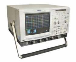
The LeCroy LC series is a line of four-channel digital storage oscilloscopes built to save engineers time in troubleshooting and problem-solving. Each unit is an integrated system that captures key events with high resolution over long time intervals, presents data on a large color CRT using advanced display techniques, and analyzes signals through a powerful processing system with math packages. An eight-trace display rounds out the picture, letting the user view any mix of channels, math functions, zooms, and reference memories at once.
These oscilloscopes target the design and debug of fast digital systems and the capture of fast transient signals, where high-speed signal acquisition is essential. The instrument captures and views fast risetime signals, and built-in math functions assist troubleshooting and diagnosis of circuit problems. Advanced waveform math, spectrum analysis, and waveform-parameter analysis increase the speed with which circuit problems are identified and solved.
ValueTronics stocks and holds its own inventory in a 20,000-square-foot secure warehouse at 1675 Cambridge Drive in Elgin, Illinois. Every pre-owned unit is inspected and functionally verified in-house before it ships, while new units leave factory-sealed exactly as received from the manufacturer, so buyers get the right instrument in the condition they expect.
LeCroy Corporation, founded in 1964, was acquired by Teledyne Technologies in 2012 and has since operated as Teledyne LeCroy.
The LC series is a family of four-channel color digital storage oscilloscopes offered in two bandwidth lines: the 500 MHz LC334A and the 1 GHz LC574A. Each line is available in three acquisition-memory configurations, identified by the base, 'M', and 'L' suffixes, so a buyer can match memory depth to the length and resolution of the signals being captured.
Across the family the architecture is consistent: four channels, a 9-inch color CRT with eight-trace display, the 96 MHz PowerPC 603e processor, SMARTMemory management, and the same standard math and spectrum-analysis processing. The models differ chiefly in bandwidth, single-shot sample rate, and acquisition memory per channel.
Each model in the LC series below links to its own dedicated product page with condition-matched pricing for the pre-owned unit you select. Choose the bandwidth and acquisition-memory configuration that fits your application, then review that page for its specific specifications and current availability.
The LC574A anchors the 1 GHz end of the family: a four-channel, 1 GS/s, 1 GHz bandwidth DSO that operates at a 4 GS/s sample rate for single-channel inputs and offers a 1 GHz trigger bandwidth, providing a flexible solution for capturing and viewing fast risetime signals.
The primary differences run along three axes shown in the comparison table. Bandwidth is 500 MHz on the LC334A line versus 1 GHz on the LC574A line; maximum single-shot sample rate reaches 2 GS/s on the LC334A line and 4 GS/s on the LC574A line; and acquisition memory per channel steps up with the suffix from 100 kpts (base) to 500 kpts ('M') to 2 Mpts ('L').
The 1 Mohm maximum input rating also differs between the lines, at 250 V for LC334A models and 400 V for LC574A models. Within the LC574A line, the internal graphics printer and Parameter Analysis Package are included, and the LC574AL additionally includes 64 MB system memory. Refer to the comparison table that follows for the exact per-model values.
| Model | Bandwidth | Max Single-Shot Sample Rate | Memory per Channel |
|---|---|---|---|
| LC334AM | 500 MHz | 2 GS/s | 500 kpts/ch |
| LC334A | 500 MHz | 2 GS/s | 100 kpts/ch |
| LC334AL | 500 MHz | 2 GS/s | 2 Mpts/ch |
| LC574A | 1 GHz | 4 GS/s | 100 kpts/ch |
Additional differences in specifications beyond the few shown above are not listed here — see each model's full specifications below.
| Specification | Value |
|---|---|
| Acquisition System | |
| No. of Channels | 4 |
| No. of Digitizers | 4 |
| Bandwidth (-3 dB) @ 50 Ω | DC to 500 MHz |
| Bandwidth (-3 dB) @ 1 MΩ | DC to 500 MHz typical at probe tip with optional 1 GHz FET probe |
| Sensitivity (50 Ω) | 2 mV/div to 5 V/div, fully variable |
| Sensitivity (1 MΩ) | 2 mV/div to 5 V/div, fully variable |
| Offset Range (2.00–9.99 mV/div) | ±120 mV |
| Offset Range (10.0–199 mV/div) | ±1.2 V |
| Offset Range (0.2–5.0 V/div) | ±24 V |
| DC Accuracy | Typical 1% |
| Vertical Resolution | 8 bits |
| Bandwidth Limiter | 30 MHz |
| Input Coupling | AC, DC, GND |
| Input Impedance | 10 MΩ // 15 pF (system capacitance using PP005) or 50 Ω ±1% |
| Max Input (50 Ω) | ±5 V DC (500 mW) or 5 V RMS |
| Max Input (1 MΩ) | 250 V |
| Acquisition Modes | |
| Random Interleaved Sampling (RIS) | For repetitive signals from 1 ns/div to 5 µs/div |
| Single Shot | For transient and repetitive signals from 10 ns/div with all channels active |
| Peak Detect | At 400 MS/s, captures high-speed events down to 1 ns while simultaneously capturing normally sampled data |
| Sequence | Stores multiple time-stamped events in segmented acquisition memories |
| Dead Time Between Segments | Typically < 30 µs, max 50 µs |
| Maximum Sample Rate and Acquisition Memory | |
| Sample Rate, All Channels (Peak Detect OFF) | 500 MS/s |
| Sample Rate, Paired Ch 2 & Ch 3 (Peak Detect OFF) | 1 GS/s |
| Sample Rate, One Channel, Paired + Adapter (Peak Detect OFF) | 2 GS/s |
| Sample Rate, Peak Detect ON (All Channels) | 100 MS/s data + 400 MS/s peaks |
| Memory/Channel, All Channels | 500k |
| Memory/Channel, Paired | 1 M |
| Memory/Channel, One Channel (Paired + Adapter) | 2 M |
| Memory/Channel, Peak Detect ON | 250k data + 250k peaks |
| Acquisition Memory Segments | 2,000 |
| Timebase System | |
| Timebases | Main and up to 4 Zoom Traces |
| Time/Div Range | 1 ns/div to 1,000 s/div |
| Clock Accuracy | ≤ 10 ppm |
| Interpolator Resolution | 10 ps |
| Roll Mode | 500 ms to 1,000 s/div; for > 50 kpoints: 10 s to 1,000 s/div |
| External Clock | ≤ 100 MHz on EXT input with ECL, TTL or zero crossing levels; optional 50 MHz to 500 MHz rear-panel fixed frequency clock input |
| External Reference | Optional 10 MHz rear-panel input |
| Triggering System | |
| Modes | Normal, Auto, Single, Stop |
| Sources | CH1, CH2, CH3, CH4, Line, EXT, EXT/10 |
| Slope | Positive, Negative |
| Coupling | AC, DC, HF, LFREJ, HFREJ |
| Pre-Trigger Recording | 0 to 100% of full scale (1% increments) |
| Post-Trigger Delay | 0 to 10,000 divisions (0.1 div increments) |
| Holdoff by Time | 10 ns to 20 s |
| Holdoff by Events | 0 to 99,999,999 |
| Internal Trigger Range | ±5 div |
| EXT Trigger Max Input | 10 MΩ // 15 pF: 50 V (DC + peak AC ≤ 10 kHz); 50 Ω ±1%: ±5 V DC (500 mW) or 5 V RMS |
| EXT Trigger Range | ±0.5 V (±5 V with EXT/10) |
| SMART Trigger Types | |
| Pattern | Logic combination of 5 inputs (CH1–CH4, EXT); each High, Low or Don't Care |
| Signal or Pattern Width | Between two limits from < 2.5 ns to 20 s; typically triggers on glitches 1 ns wide |
| Signal or Pattern Interval | Between two limits from 10 ns to 20 s |
| Dropout | Time-out from 25 ns to 20 s |
| State/Edge Qualified | Trigger on a source only if a given state or transition occurred on another source |
| TV | Line (up to 1500) and field (up to 8) for PAL (SECAM), NTSC or nonstandard video |
| Exclusion Trigger | Triggers only on aberrations shorter or longer than normal |
| Signal Viewing | |
| Display Type | Color 9" Raster Scan CRT, 0.26 mm dot pitch |
| Resolution | 640 x 480 points |
| Display Area | 170 mm x 125 mm |
| Grid Styles | Single, Dual, Quad, Octal, XY, Single+XY, Dual+XY, Full Screen |
| Waveform Style | Dot Join with optional sample point highlight, or Dots only |
| Persistence Modes | Color-graded and Analog Persistence, infinite or variable with decay; 64 k levels |
| Number of Traces | 8 (any mix of channels, memories or Math functions) |
Important: Maximum input at 1 Mohm: 250 V on LC334A models and 400 V (DC + peak AC <= 10 kHz) on LC574A models. Maximum input at 50 ohm: +/-5 V DC (500 mW) or 5 V RMS.
Important: Analog Persistence is only available in four channel mode on LC334A models.
Important: An internal, high-resolution graphics printer for screen dumps is standard in the "L" models.
Important: The LC574A, LC574AM and LC574AL include an Internal Graphics Printer and the Parameter Analysis Package.
Important: The Internal Graphics Printer (GP01) and 64 Mbyte System Memory (64MBSM) are included with the LC574AL.
Important: Maximum horizontal zoom factor varies by model and channel combination; verify the installed capability on your specific instrument.
Recommended pairing: alongside the standard PP005 10:1 passive probes supplied one per channel, the AP020 1 GHz 10:1 FET probe and AP022 2.5 GHz active probe are available probe options for higher-bandwidth probing.
This pre-owned unit is inspected and functionally verified in-house before it ships and is backed by our pre-owned warranty. To confirm its exact condition, firmware revision, installed options, or included accessories for your application before ordering, contact our Test Architects.
ValueTronics supplies both new and used test and measurement equipment. New units ship factory-sealed, exactly as received from the manufacturer; every used unit is inspected and functionally verified in-house at our 20,000 sq ft secure facility in Elgin, Illinois before it ships. Our Test Architects can help you select the condition, calibration, and configuration that fit your application.
Please review the Manufacturer's Data Sheet to verify published specifications. Feedback on this webpage is always welcome — please reach out to your Test Architect at any time for questions or concerns. Thank you, we truly appreciate you being our customer.
Model No
LeCroy
Condition
Pre-Owned
Manufacturer
LeCroy
Osc_ch
4
Osc_freq
500 MHz
Osc_r
50 Ω / 10 MΩ
Osc_sampl
500 MS/s

30+ Years in Business
Secure Payments
Sell Test Equipments
Knowledgeable Staff
On-site Lab
30+ Years in Business
Secure Payments
Sell Test Equipments
Knowledgeable Staff
On-site Lab
Request A Quote
 Chat Live
 Contact Us
 sales@valuetronics.com