


🎓 Request a Quote To Get An EDU Discount
Couldn't load pickup availability
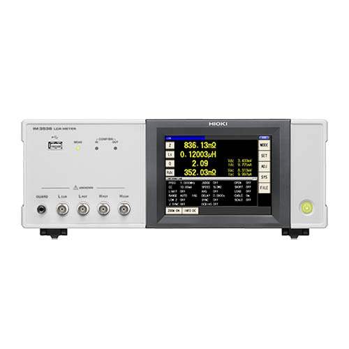
The IM3536 is a general-purpose LCR meter for measuring electronic components such as capacitors and inductors. It brings together a broad measurement frequency span of DC and 4 Hz to 8 MHz with a guaranteed accuracy range that starts at 1 mΩ and extends to 200 MΩ, serving a wide range of applications from R&D through production lines.
Across development and research work, the IM3536 supports measurement under varied conditions — for example analyzing a coil's resonance point while sweeping frequency, or evaluating a sample that exhibits signal dependency by changing the measurement signal during the test. Named applications include electrolytic capacitor low-ESR measurement and power supply coil impedance testing, which demands strong frequency characteristics. On the production side it offers comparator (Hi/IN/Lo) and BIN judgment for component sorting, plus a continuous measurement mode that runs one component through multiple saved condition sets in a single test session.
ValueTronics stocks and holds its own inventory in a 20,000 sq ft secure warehouse at 1675 Cambridge Drive, Elgin, Illinois.
| Specification | Value |
|---|---|
| Measurement Parameters (LCR mode) | |
| Z | Impedance |
| Y | Admittance |
| θ | Phase angle |
| X | Reactance |
| G | Conductance |
| B | Susceptance |
| Q | Q-factor |
| Rdc | DC resistance |
| Rs | Equivalent series resistance (ESR) |
| Rp | Equivalent parallel resistance |
| Ls | Equivalent series inductance |
| Lp | Equivalent parallel inductance |
| Cs | Equivalent series capacitance |
| Cp | Equivalent parallel capacitance |
| D | Loss factor tan δ |
| σ | Conductivity |
| ε | Permittivity |
| Display Range | |
| Z | 0.00 mΩ to 9.99999 GΩ |
| Y | 0.000 nS to 9.99999 GS |
| θ | ±(0.000° to 180.000°) |
| X | ±(0.00 mΩ to 9.99999 GΩ) |
| G | ±(0.000 nS to 9.99999 GS) |
| B | ±(0.000 nS to 9.99999 GS) |
| Q | ±(0.00 to 9999.99) |
| Rdc | ±(0.00 mΩ to 9.99999 GΩ) |
| Rs | ±(0.00 mΩ to 9.99999 GΩ) |
| Rp | ±(0.00 mΩ to 9.99999 GΩ) |
| Ls | ±(0.00000 μH to 9.99999 GH) |
| Lp | ±(0.00000 μH to 9.99999 GH) |
| Cs | ±(0.0000 pF to 9.99999 GF) |
| Cp | ±(0.0000 pF to 9.99999 GF) |
| D | ±(0.00000 to 9.99999) |
| Δ% | ±(0.000% to 999.999%) |
| σ | ±(0.00000 to 999.999 G) |
| ε | ±(0.00000 to 999.999 G) |
| Measurement Range and Signal | |
| Measurable range | 1 mΩ to 200 MΩ |
| Output impedance | Normal mode: 100 Ω, Low impedance high accuracy mode: 10 Ω |
| Measurement frequency range | 4 Hz to 8 MHz |
| Frequency resolution: 4.00 Hz to 999.99 Hz | 10 mHz steps |
| Frequency resolution: 1.0000 kHz to 9.9999 kHz | 100 mHz steps |
| Frequency resolution: 10.000 kHz to 99.999 kHz | 1 Hz steps |
| Frequency resolution: 100.00 kHz to 999.99 kHz | 10 Hz steps |
| Frequency resolution: 1.0000 MHz to 8.0000 MHz | 100 Hz steps |
| Frequency accuracy | ±0.01% of setting or less |
| Measurement signal level [V/CV mode], Normal mode, 4 Hz to 1.0000 MHz | 10 mV to 5 V rms (maximum 50 mA) |
| Measurement signal level [V/CV mode], Normal mode, 1.0001 MHz to 8 MHz | 10 mV to 1 V rms (maximum 10 mA) |
| Measurement signal level [V/CV mode], Low impedance high accuracy mode, 4 Hz to 1.0000 MHz | 10 mV to 1 V rms (maximum 100 mA) |
| Signal level resolution: 10 mV rms to 1.000 V rms | 1 mV rms steps |
| Signal level resolution: 1.01 V rms to 5 V rms | 10 mV rms steps |
| Measurement signal level [CC mode], Normal mode, 4 Hz to 1.0000 MHz | 10 μA to 50 mA rms (maximum 5 V) |
| Measurement signal level [CC mode], Normal mode, 1.0001 MHz to 8 MHz | 10 μA to 1 mA rms (maximum 1 V) |
| Measurement signal level [CC mode], Low impedance high accuracy mode, 4 Hz to 1.0000 MHz | 10 μA to 100 mA rms (maximum 1 V) |
| CC mode resolution | 10 μA rms steps |
| Monitor function | Monitor voltage range: 0.000 V to 5.000 V rms; Monitor current range: 0.000 mA to 100.0 mA rms |
| DC resistance measurement signal level | Fixed at 1 V |
| DC bias measurement generating range | DC voltage 0 V to 2.50 V (10 mV resolution); In low Z high accuracy mode: 0 V to 1 V (10 mV resolution) |
| Accuracy | |
| Basic accuracy | Z: ±0.05% rdg.; θ: ±0.03° (representative value) |
| Guaranteed accuracy range | 1 mΩ to 200 MΩ (impedance) |
| Guaranteed accuracy period | 1 year |
| Warm-up time | 60 minutes |
| Terminal structure | 4-terminal structure |
| Measurement Functions | |
| Measurement modes | LCR mode: Measurement using a single set of conditions. Continuous measurement mode: Continuous measurement using previously saved conditions |
| Measurement speed | FAST / MED / SLOW / SLOW2 |
| Averaging | Valid setting range: 1 to 256 (in steps of 1) |
| Trigger function | Internal trigger and External trigger (sources: manual, communications commands, EXT. I/O) |
| Trigger delay | 0.0000 s to 9.9999 s |
| Trigger synchronous output wait time | 0.0000 s to 9.9999 s |
| Comparator measurement | Hi, IN, and Lo judgments for 2 parameters |
| BIN measurement | 10 categories for 2 measurement parameters |
| Continuous measurement maximum number | 60 |
| Display digits setting | 3 to 6 digits |
| Compensation Function | |
| Open/short compensation | Yes |
| Load compensation | Number of sets of compensation conditions: Up to 5 |
| Cable length compensation | Cable length settings: 0 m, 1 m, 2 m, 4 m |
| Correlation compensation | Compensation of display values based on user-input compensation coefficient |
| Contact check | 4-terminal contact check; High-Z reject function (detection of OPEN state during 2-terminal measurement) |
| Display, Recording and Interface | |
| Display | 5.7-inch color TFT with touch panel |
| Memory function | Measurement result items (maximum 32000 items) can be saved to the instrument |
| Panel save and load functions | Measurement conditions: Up to 60; Compensation values: Up to 128 |
| Interfaces | EXT. I/O (HANDLER), USB, USB flash drive, LAN, GP-IB, RS-232C |
| BCD output | Output from EXT. I/O connector; generates BCD output for the No.1 and No.3 parameter measured values |
| USB | USB Type B receptacle; USB2.0 (High Speed) |
| LAN | RJ-45 connector; 10Base-T/100Base-T automatic detection; TCP/IP |
| GP-IB | 24-pin Centronics type connector; IEEE-488.1 1987; Reference IEEE-488.2 1987; Terminator LF, CR+LF |
| RS-232C | D-sub 9-pin connector; Hardware/Software flow control; 9600, 19200, 38400, 57600 bps |
| EXT. I/O Electrical Specifications | |
| Input type | Optocoupler-isolated, non-voltage contact inputs (current sink, active-low) |
| Input asserted (on) voltage | 0.9 V or less |
| Input de-asserted (off) voltage | OPEN or 5 V to 24 V |
| Input asserted (on) current | 3 mA/ch |
| Maximum applied voltage (input) | 30 V |
| Output type | Isolated NPN open-collector outputs (current sink, active-low) |
| Maximum load voltage | 30 V |
| Maximum output current | 50 mA/ch |
Important: This product is not supplied with measurement probes or test fixtures — select and purchase the probe or test fixture option appropriate for your application separately.
Important: The DC BIAS VOLTAGE UNIT 9268-10 (measurement frequency range 40 Hz to 8 MHz, maximum applied voltage ±40 V DC) requires a separate external DC bias power supply.
Important: For an RS-232C connection, a crossover cable can be used; the RS-232C CABLE 9637 can be used without hardware flow control.
Recommended pairing: the SMD TEST FIXTURE 9677, a direct-connection fixture rated DC to 120 MHz for surface-mount components sized 0402 to 0603 (EIA) / 1005 to 1608 (JIS).
This is a brand-new, factory-sealed unit, supplied exactly as it arrives from the manufacturer and backed by the full manufacturer warranty. For the exact configuration, available options, included accessories, or current lead time for your application, our Test Architects can confirm the details before you order.
ValueTronics supplies both new and used test and measurement equipment. New units ship factory-sealed, exactly as received from the manufacturer; every used unit is inspected and functionally verified in-house at our 20,000 sq ft secure facility in Elgin, Illinois before it ships. Our Test Architects can help you select the condition, calibration, and configuration that fit your application.
Please review the Manufacturer's Data Sheet to verify published specifications. Feedback on this webpage is always welcome — please reach out to your Test Architect at any time for questions or concerns. Thank you, we truly appreciate you being our customer.
Model No
Hioki
Condition
Factory New
Manufacturer
Hioki
Lcr_met_freq
DC, 4 Hz to 8 MHz
IM9100 Hioki Accessory New
IM9100
IM9110 Hioki Accessory New
IM9110
L2000 Hioki Test Lead New
L2000
Hioki L2001 Pincher Probe for IM3536 LCR Meter
L2001
IM9902 Hioki Accessory New
IM9902
IM9901 Hioki Accessory New
IM9901

30+ Years in Business
Secure Payments
Sell Test Equipments
Knowledgeable Staff
On-site Lab
30+ Years in Business
Secure Payments
Sell Test Equipments
Knowledgeable Staff
On-site Lab
Request A Quote
 Chat Live
 Contact Us
 sales@valuetronics.com
