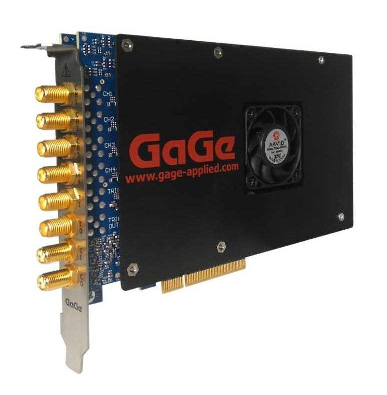
The GaGe RazorMax Express is a 16-bit PCIe Gen3 streaming digitizer family designed for wideband signal capture at sampling rates up to 1 GS/s per channel. Available in 2-channel and 4-channel configurations, the RazorMax Express combines 16-bit vertical resolution with 700 MHz analog bandwidth (on 1 GS/s models) and a dual-port onboard memory architecture that supports sustained data streaming to the host PC at rates up to 6 GB/s over a PCIe Gen3 x8 interface.
The datasheet identifies application areas including wideband signal analysis, RADAR design and test, signals intelligence (SIGINT), ultrasonic non-destructive testing, LIDAR systems, communications, optical coherence tomography, spectroscopy, high-performance imaging, time of flight, life sciences, and particle physics. A digitizer in this class converts analog input waveforms into time-sampled digital data so the captured signal can be analyzed, recorded, or processed by a host computer or onboard FPGA.
ValueTronics International operates from a 20,000 square foot secure warehouse at 1675 Cambridge Drive in Elgin, Illinois, where every instrument is received, tested, graded, and prepared for shipment by our own technicians before it leaves the building. We are not a drop-shipper or a pass-through broker: the digitizer you order has been physically inspected at our facility, its specifications verified against published manufacturer data, and its accessories confirmed by name. That difference is what separates a {{CONDITION}} RazorMax Express from ValueTronics from an unverified marketplace listing or a catalog reseller that never touches the hardware it sells.
GaGe is a product brand of DynamicSignals LLC, an ISO 9001:2015 certified company. The brand has been associated with high-speed PC-based digitizer instrumentation for several decades and has carried through successive corporate ownership while retaining the GaGe product identity used on this datasheet.
The RazorMax Express family covers four primary hardware configurations differentiated by channel count and maximum sampling rate. All four models share the same 16-bit vertical resolution, 4 GS (8 GB) of standard onboard dual-port acquisition memory, 50 Ohm SMA inputs, PCIe Gen3 x8 host interface, and identical triggering, clocking, multi-card, and timestamping architectures as described in the datasheet.
The differentiators between models are channel count (2 versus 4) and maximum per-channel sampling rate, which in turn sets the analog input bandwidth: 1 GS/s models carry 700 MHz of analog bandwidth and 500 MS/s models carry 350 MHz. Each base model is also available in a low-range (LR) variant with a factory-configured plus or minus 240 millivolt input range in place of the standard plus or minus 1 volt range.
Each new RazorMax Express model below is listed on its own product page with condition-matched pricing and an availability status set against the specific unit in our inventory. Selecting the correct model is a function of how many input channels you need to capture simultaneously, the maximum signal frequency you intend to digitize, and whether your input signal levels are better suited to the standard plus or minus 1 volt range or the lower plus or minus 240 millivolt range.
The 500 MS/s models (CSE16502 and CSE16504) are specified at 350 MHz analog bandwidth and are well aligned with applications whose signal content is contained within that frequency range. The 1 GS/s models (CSE161G2 and CSE161G4) are specified at 700 MHz analog bandwidth and, per the datasheet, are particularly applicable to RF-based applications that benefit from direct RF sampling of wider band signals.
Channel count separates the 2-channel configurations from the 4-channel configurations. Because the standard 4 GS (8 GB) onboard memory is shared and equally divided among active channels, a 2-channel model dedicates more memory per channel during multi-channel capture than the equivalent 4-channel model. The comparison table that follows summarizes the channel count, maximum sampling rate, analog bandwidth, input range option, and memory configuration as printed on the datasheet.
| Model | Input Channels | Max Sampling Rate | Input Bandwidth |
|---|---|---|---|
| CSE161G2 | 2 | 1 GS/s | 700 MHz |
| CSE16502 | 2 | 500 MS/s | 350 MHz |
| CSE16502-LR | 2 | 500 MS/s | 350 MHz |
| CSE16504 | 4 | 500 MS/s | 350 MHz |
Additional differences in specifications beyond the few shown above are not listed here — see each model's full specifications below.
| Category | Specification | Value |
|---|---|---|
| Main | Vertical Resolution | 16-bit |
| Main | Onboard Acquisition Memory | 4 GS (8 GB), Dual Port, Data Streaming supported. Memory shared and equally divided among all active input channels (4, 2, or 1). |
| Analog Inputs | Connectors | SMA |
| Analog Inputs | Impedance | 50 Ω |
| Analog Inputs | Coupling | DC (standard) or AC (option) |
| Analog Inputs | Analog Bandwidth | DC to 700 MHz at 1 GS/s; DC to 350 MHz at 500 MS/s |
| Analog Inputs | Voltage Ranges | ±1 V Fixed or ±240 mV Fixed (use optional inline SMA attenuators for additional effective input ranges) |
| Analog Inputs | DC User Offset (software selectable) | Spans Full Scale Input Range (FSIR) |
| Analog Inputs | Absolute Max. Input | ±3 V (over-voltage protection included) |
| A/D Sampling | Rates per Channel (software selectable) | 1 GS/s, 875 MS/s, 800 MS/s, 750 MS/s, 650 MS/s, 600 MS/s, 525 MS/s, 500 MS/s, 425 MS/s, 400 MS/s, 375 MS/s, 325 MS/s, 300 MS/s, 250 MS/s, 200 MS/s, 100 MS/s, 50 MS/s, 20 MS/s, 10 MS/s, 5 MS/s, 2 MS/s, 1 MS/s, 500 kS/s, 200 kS/s, 100 kS/s, 50 kS/s, 20 kS/s, 10 kS/s, 5 kS/s, 2 kS/s, 1 kS/s |
| A/D Sampling | Rate Accuracy | ±1 part-per-million (0° to 50° C ambient) |
| Performance | ENOB @ 10 MHz (±1 V, DC, 50 Ω, 1 GS/s) | 11.1 Bits |
| Performance | ENOB @ 70 MHz | 11.02 Bits |
| Performance | ENOB @ 199 MHz | 10.36 Bits |
| Performance | ENOB @ 401 MHz | 10.55 Bits |
| Performance | SNR @ 10 MHz / 70 MHz / 199 MHz / 401 MHz | 68.92 / 69.94 / 69.14 / 66.86 dB |
| Performance | THD @ 10 MHz / 70 MHz / 199 MHz / 401 MHz | -75.42 / -70.29 / -62.93 / -68.24 dB |
| Performance | SINAD @ 10 MHz / 70 MHz / 199 MHz / 401 MHz | 68.69 / 68.19 / 64.21 / 65.43 dB |
| Performance | SFDR @ 10 MHz / 70 MHz / 199 MHz / 401 MHz | 81.36 / 71.14 / 62.85 / 68.53 dB |
| Performance | RMS Noise | ~0.7 mV RMS |
| Triggering | Engines | 2 per Channel, 1 for External Trigger |
| Triggering | Source | Any Input Channel, External Trigger or Software |
| Triggering | Input Combination | All Combinations of Sources Logically OR'ed |
| Triggering | Slope | Positive or Negative (software selectable) |
| Triggering | Sensitivity | ±5% of Full Scale Input Range of Trigger Source. Signal amplitude must be at least 10% of full scale to cause a trigger to occur. Smaller signals are rejected as noise. |
| Triggering | Post-Trigger Data | 32 points minimum. Can be defined with 32 point resolution. |
| External Trigger | Connector | SMA |
| External Trigger | Impedance | ≈ 1k Ω |
| External Trigger | Coupling | AC |
| External Trigger | Bandwidth | >100 MHz |
| External Trigger | Voltage Range | 0-3 V (unipolar) |
| Trigger Out | Connector | SMA |
| Trigger Out | Impedance | 50 Ω |
| Trigger Out | Amplitude | 0 – TTL |
| Clock In | Connector | SMA |
| Clock In | Signal Level | Minimum 0.2 V RMS, Maximum 0.5 V RMS |
| Clock In | Impedance | 50 Ω |
| Clock In | Coupling | DC |
| Clock In | Duty Cycle | 50% ±5% |
| Clock In | Input Modes | External Clock or 10 MHz Reference Clock |
| Clock In | External Clock Mode Rates | Minimum 250 MHz, Maximum 1 GHz |
| Clock In | External Reference Clock Mode Rate | 10 MHz ±1000 ppm; the external reference time base is used to synchronize the internal sampling clock. |
| Clock In | Variable/Inactive External Clock Mode | Supports variable rate k-clocking or inactive external clock, particularly useful for OCT applications. |
| Clock Out | Connector | SMA |
| Clock Out | Signal Level | 0 – 1.5 V |
| Clock Out | Impedance | 50 Ω Compatible |
| Clock Out | Duty Cycle | 50% |
| Clock Out | Output Modes | Maximum Sampling Clock Frequency or 10 MHz Reference Clock |
Please review the Manufacturer's Data Sheet to verify published specifications. Feedback on this webpage is always welcome — please reach out to your Test Architect at any time for questions or concerns. Thank you, we truly appreciate you being our customer.
Model No
GaGe
Condition
New
Manufacturer
Cse161g2

30+ Years in Business
Secure Payments
Sell Test Equipments
Knowledgeable Staff
On-site Lab
30+ Years in Business
Secure Payments
Sell Test Equipments
Knowledgeable Staff
On-site Lab
Request A Quote
 Chat Live
 Contact Us
 sales@valuetronics.com