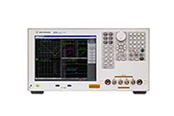
The Keysight E4990A Impedance Analyzer measures impedance parameters across a frequency range from 20 Hz up to 120 MHz, depending on the configured upper-frequency option. The instrument supports a comprehensive set of impedance and admittance parameters — |Z|, θz, |Y|, θy, Cp, Cs, Lp, Ls, Rp, Rs, D, Q, X, G, B, and complex Z and Y — along with AC and DC voltage and current level monitoring. A four-terminal pair measurement configuration with BNC connectors provides the foundation for low-impedance and high-impedance characterization, and Option 120 units can be reconfigured to a single-port test interface using the 42942A Terminal Adapter (7 mm port) or the 42941A Impedance Probe (SMA port).
Engineers use the E4990A for component characterization, materials research, and frequency-dependent impedance analysis. The published specifications cover applications including capacitor and inductor measurement under DC bias, equivalent circuit parameter extraction (3-component and 4-component models with frequency-response simulation), and production component sorting via the integrated 36-pin handler interface. The signal level monitor reports actual voltage and current at the device under test, supporting measurements where the test signal must be precisely controlled — including DC voltage bias to ±40 V and DC current bias to ±100 mA, with constant-voltage and constant-current bias modes for active and reactive device evaluation.
ValueTronics International stocks, inspects, and tests precision impedance analyzers like the E4990A in our 20,000 sq ft facility at 1675 Cambridge Drive, Elgin, Illinois. Every used instrument we ship is bench-verified by our technicians before it leaves the building, and every quote we send carries a direct contact path back to the person who built it. This is the model we have operated since 1992: deep test-and-measurement expertise across roughly 120 manufacturers, in-house inspection rather than drop-shipped surplus, and accountability that you can call back when a question arises after delivery.
Keysight Technologies was formed in 2014 when Agilent Technologies divided its operations and spun off its electronic measurement business as a standalone company. Agilent itself was created in 1999 from Hewlett-Packard's measurement, semiconductor, and life-sciences divisions. Impedance analyzers in this product family carry forward a measurement-instrument lineage that traces from Hewlett-Packard through Agilent to Keysight.
| Category | Parameter | Specification |
|---|---|---|
| Basic Measurement | Impedance parameters | |Z|, θz, |Y|, θy, Cp, Cs, Lp, Ls, Rp, Rs (R), D, Q, X, G, B, Complex Z, Complex Y |
| Basic Measurement | Level monitor | Vac, Iac, Vdc, Idc |
| Measurement terminal | Configuration | Four-terminal pair configuration |
| Measurement terminal | Connector type | Four BNC (female) connectors. Option 120: Can be converted to one port terminal using the Keysight 42942A Terminal Adapter (7-mm port) or 42941A Impedance Probe (SMA (f) port). |
| Source Frequency | Range | 20 Hz to 120 MHz (Option 120); 20 Hz to 50 MHz (Option 050); 20 Hz to 30 MHz (Option 030); 20 Hz to 20 MHz (Option 020); 20 Hz to 10 MHz (Option 010) |
| Source Frequency | Resolution | 1 mHz |
| Source Frequency | Accuracy (without Option 1E5) | ± 7 ppm ± 1 mHz (at 23 ± 5 °C) |
| Source Frequency | Accuracy (with Option 1E5) | ± 1 ppm ± 1 mHz (at 23 ± 5 °C) |
| Source Frequency | Stability (without Option 1E5) | ± 7 ppm (at 5 to 40 °C, Typical) |
| Source Frequency | Stability (with Option 1E5) | ± 0.5 ppm (at 5 to 40 °C, Typical); ± 0.5 ppm per year (Typical) |
| Voltage Signal Level | Range | 5 mVrms to 1 Vrms |
| Voltage Signal Level | Resolution | 1 mV |
| Voltage Signal Level | Accuracy (4-terminal pair / 7-mm port of 42942A) | ± [(10 + 0.05 × f)% + 1 mV] |
| Voltage Signal Level | Accuracy (42941A / 16048G/H) | ± [(15 + 0.1 × f)% + 1 mV] |
| Current Signal Level | Range | 200 µArms to 20 mArms |
| Current Signal Level | Resolution | 20 µA |
| Output Impedance | Output impedance | 25 Ω (nominal) |
| DC Bias | DC voltage bias range | 0 to ± 40 V |
| DC Bias | DC voltage bias resolution | 1 mV |
| DC Bias | DC voltage bias accuracy | ± [0.1% + (5 + 30 × |Imon|) mV] |
| DC Bias | DC current bias range | 0 to ± 100 mA |
| DC Bias | DC current bias resolution | 40 µA |
| DC Bias | DC current bias accuracy | ± [2% + (0.2 + |Vmon|/20) mA] |
| DC Bias | Output impedance | 25 Ω (nominal) |
| Sweep | Available sweep parameters | Frequency, signal voltage, signal current, DC bias voltage, DC bias current |
| Sweep | Sweep type | Linear frequency, log frequency, OSC level (voltage, current), DC bias (voltage, current), log DC bias (voltage, current) |
| Sweep | Sweep direction | Up sweep, down sweep |
| Sweep | Number of measurement points | 2 to 1601 points |
| Sweep | Number of segments | 1 to 201 |
| Sweep | Delay time range | 0 sec to 30 sec |
| Sweep | Delay time resolution | 1 msec |
| Trigger | Trigger type | Continuous, single, averaging |
| Trigger | Trigger source | Internal (free run), external (BNC connector input), GPIB/USB/LAN, manual (Front key) |
| Trigger | Trigger event type | Point trigger, Sweep trigger |
| Measurement Time | Range | 1 (fast) to 5 (precise), 5 steps |
| Averaging | Type | Sweep-to-sweep averaging, point averaging |
| Averaging | Averaging factor | 1 to 999 (integer) |
| Display | Size/type | 10.4-inch color LCD (TFT) |
| Display | Number of pixels | 1024 x 768 (XGA) |
| Display | Data traces | 4 traces per channel |
| Display | Memory traces | 4 traces per channel |
| Marker | Marker count | 10 independent markers per trace |
| Equivalent Circuit | Circuit model | 3-component model (4 models), 4-component model (3 models) |
| Interfaces | GPIB | 24-pin D-Sub (Type D-24), female; compatible with IEEE-488 |
| Interfaces | USB host port | Universal serial bus jack, Type A; female |
| Interfaces | USB (USBTMC) interface port | Type B (4 contacts inline); compatible with USBTMC-USB488 and USB 2.0 |
| Interfaces | LAN | 10/100/1000 Base T Ethernet, 8-pin configuration |
| Interfaces | Video output | 15-pin mini D-Sub; female; drives VGA compatible monitors |
| Handler Interface | Connector type | 36-pin centronics, female |
| Handler Interface | Signal type | Negative logic, opto-isolated, open collector output |
| Measurement Circuit Protection | Max discharge withstand voltage | 1000 V @ C < 2 µF, √(2/C) V @ C ≥ 2 µF |
| Operating Environment | Temperature | +5 °C to +40 °C |
| Operating Environment | Humidity | 20% to 80% at wet bulb temperature < +29 °C (non-condensation) |
| Operating Environment | Altitude | 0 to 2,000 m (0 to 6561 feet) |
| Operating Environment | Vibration | 0.21 Grms maximum, 5 Hz to 500 Hz |
| Non-operating Environment | Temperature | -10 °C to +60 °C |
| Non-operating Environment | Humidity | 20% to 90% at wet bulb temperature < +40 °C (non-condensation) |
| Non-operating Environment | Altitude | 0 to 4,572 m (0 to 15,000 feet) |
| Non-operating Environment | Vibration | 2.09 Grms maximum, 5 to 500 Hz |
| External Reference Input | Frequency | 10 MHz ± 10 ppm (Typical) |
Please review the Manufacturer's Data Sheet to verify published specifications. Feedback on this webpage is always welcome — please reach out to your Test Architect at any time for questions or concerns. Thank you, we truly appreciate you being our customer.
Model No
Keysight
Condition
Used
Manufacturer
Agilent
E4990A-010
20 Hz to 10 MHz
E4990A-020
20 Hz to 20 MHz
E4990A-030
20 Hz to 30 MHz
E4990A-050
20 Hz to 50 MHz
E4990A-120
20 Hz to 120 MHz
E4990A-1E5
High stability timebase

30+ Years in Business
Secure Payments
Sell Test Equipments
Knowledgeable Staff
On-site Lab
30+ Years in Business
Secure Payments
Sell Test Equipments
Knowledgeable Staff
On-site Lab
Request A Quote
 Chat Live
 Contact Us
 sales@valuetronics.com