


🎓 Request a Quote To Get An EDU Discount
Couldn't load pickup availability
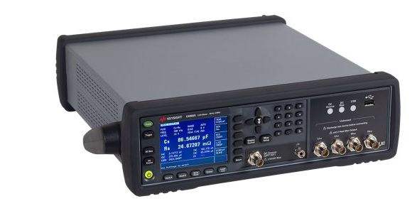
The Keysight E4980A and E4980AL are precision LCR meters built for impedance characterization of passive components and materials. The E4980A covers a test-frequency span of 20 Hz to 2 MHz, while the E4980AL is offered in three upper-frequency variants — 300 kHz (E4980AL-032), 500 kHz (E4980AL-052), and 1 MHz (E4980AL-102) — each also starting from 20 Hz. Throughout the series, measurements are made through a four-terminal pair connection, and results are reported in a broad selection of parameter pairs covering capacitance, inductance, resistance, impedance, and admittance.
An LCR meter applies a known AC test signal to a device under test and measures the resulting voltage and current to derive impedance and its related quantities. The E4980A/E4980AL report measurement parameters including Cp-D, Cp-Q, Cp-G, Cp-Rp, Cs-D, Cs-Q, Cs-Rs, Lp-D, Lp-Q, Lp-Rp, Ls-Rs, R-X, Z-θ, G-B, and Y-θ, with both parallel and series equivalent-circuit models available. A deviation measurement function can output the difference from a reference value or the percentage deviation, and a comparator with bin-sort capability can sort the primary parameter into nine BINs plus OUT_OF_BINS, AUX_BIN, and LOW_C_REJECT categories.
Keysight Technologies traces its test-and-measurement heritage to Hewlett-Packard, whose instrument business was spun out as Agilent Technologies in 1999. That measurement business was subsequently established as Keysight Technologies in 2014, the brand under which this product line is offered today.
The E4980A is the 20 Hz to 2 MHz frequency-range LCR meter, while the E4980AL is offered with upper frequency limits of 20 Hz to 300 kHz, 500 kHz, or 1 MHz, identified by the option suffixes -032, -052, and -102 respectively. All members of the series share the four-terminal pair measurement architecture, the same broad set of measurement parameters, and OPEN/SHORT/LOAD compensation.
Option availability differs between the two model lines. The Power and DC Bias Enhancement (Option 001) is installable on the E4980A but not on the E4980AL. DCR measurement is an installable option (Option 200) on the E4980A and is equipped by default on the E4980AL. The handler interface (Option 201) and scanner interface (Option 301) are installable on both.
Each model in the series below links to its own dedicated product page with condition-matched pricing. Choose the model whose upper frequency limit and installed options fit your application; the new unit you select is priced and described for its specific condition.
The E4980A is the broadest-frequency model in the family, covering the full 20 Hz to 2 MHz span. It is the model that accepts the Power and DC Bias Enhancement (Option 001) for test signals up to 20 Vrms and variable DC bias from –40 V to +40 V, and it supports DCR measurement when Option 200 is installed.
The principal difference across the family is the upper test-frequency limit: 2 MHz on the E4980A, 1 MHz on the E4980AL-102, 500 kHz on the E4980AL-052, and 300 kHz on the E4980AL-032, with every model sharing the same 20 Hz lower limit. The comparison table that follows lists each model's frequency range alongside its option compatibility.
Beyond frequency coverage, the models differ in which options they accept, as shown in the table: the Power and DC Bias Enhancement option is specific to the E4980A, whereas DCR measurement is built into the E4980AL by default and added via option on the E4980A. The handler and scanner interface options apply across both model lines.
| Model | Frequency Range | Basic Accuracy | Test Signal Voltage |
|---|---|---|---|
| E4980A | 20 Hz to 2 MHz | 0.05% | 0 Vrms - 2.0 Vrms |
| E4980AL | 20 Hz to 1 MHz | 0.05% | 0 Vrms - 2.0 Vrms |
| E4980AL | 20 Hz to 500 kHz | 0.05% | 0 Vrms - 2.0 Vrms |
| E4980AL | 20 Hz to 300 kHz | 0.05% | 0 Vrms - 2.0 Vrms |
Additional differences in specifications beyond the few shown above are not listed here — see each model's full specifications below.
| Specification | Value |
|---|---|
| Measurement Functions | |
| Measurement parameters | Cp-D, Cp-Q, Cp-G, Cp-Rp, Cs-D, Cs-Q, Cs-Rs, Lp-D, Lp-Q, Lp-G, Lp-Rp, Lp-Rdc, Ls-D, Ls-Q, Ls-Rs, Ls-Rdc, R-X, Z-θd, Z-θr, G-B, Y-θd, Y-θr, Vdc-Idc |
| Equivalent circuits for measurement | Parallel, Series |
| Impedance range selection | Auto (auto range mode), manual (hold range mode) |
| Trigger mode | Internal (INT), manual (MAN), external (EXT), GPIB (BUS) |
| Trigger delay time | 0 s - 999 s |
| Measurement terminal | Four-terminal pair |
| Test cable length | 0 m, 1 m, 2 m, 4 m |
| Measurement time modes | Short mode, medium mode, long mode |
| Averaging | 1 - 256 measurements |
| Test Signal | |
| Test frequencies | 20 Hz - 2 MHz (E4980A); 20 Hz - 1 MHz (E4980AL-102); 20 Hz - 500 kHz (E4980AL-052); 20 Hz - 300 kHz (E4980AL-032) |
| Test frequency measurement accuracy | ±0.01% |
| Test signal modes | Normal, Constant |
| Test signal voltage range | 0 Vrms - 2.0 Vrms |
| Test signal voltage accuracy (Normal) | ± (10% + 1 mVrms) |
| Test signal voltage accuracy (Constant) | ± (6% + 1 mVrms) |
| Test signal current range | 0 Arms - 20 mArms |
| Test signal current accuracy (Normal) | ± (10% + 10 µArms) |
| Test signal current accuracy (Constant) | ± (6% + 10 µArms) |
| Output impedance | 100 Ω (nominal) |
| Test signal voltage monitor accuracy (≤ 1 MHz) | ±(3% of reading value + 0.5 mVrms) |
| Test signal current monitor accuracy (≤ 1 MHz) | ± (3% of reading value + 5 µArms) |
| Measurement Display Ranges | |
| Cs, Cp | ±1.000000 aF to 999.9999 EF |
| Ls, Lp | ±1.000000 aH to 999.9999 EH |
| D | ±0.000001 to 9.999999 |
| Q | ±0.01 to 99999.99 |
| R, Rs, Rp, X, Z, Rdc | ±1.000000 aΩ to 999.9999 EΩ |
| G, B, Y | ±1.000000 aS to 999.9999 ES |
| Vdc | ±1.000000 aV to 999.9999 EV |
| Idc | ±1.000000 aA to 999.9999 EA |
| θr | ±1.000000 arad to 3.141593 rad |
| θd | ±0.0001 deg to 180.0000 deg |
| Δ% | ±0.0001% to 999.9999% |
| Accuracy | |
| Basic accuracy (Ab) | 0.05% |
| DC Bias Signal (Standard) | |
| Test signal voltage range | 0 V to +2 V |
| Resolution | 0 V / 1.5 V / 2 V only |
| Accuracy | 0.1% + 2 mV (23°C ± 5°C); (0.1% + 2 mV) × 4 (0 to 18°C or 28 to 55°C) |
| Output impedance | 100 Ω (nominal) |
| DC bias test signal current (1.5 V/2.0 V) | Output current: Max. 20 mA |
| Compensation Function | |
| Compensation types | OPEN compensation, SHORT compensation, LOAD compensation |
| List Sweep | |
| Points | Maximum of 201 points |
| Comparator Function | |
| Bin sort (primary parameter) | 9 BINs, OUT_OF_BINS, AUX_BIN, LOW_C_REJECT |
| Bin sort (secondary parameter) | HIGH, IN, LOW |
| BIN count | Countable from 0 to 999999 |
| Measurement Assistance / Interfaces | |
| Data buffer function | Up to 201 measurement results read out in a batch |
| Save/Recall function | Up to 10 setup conditions to/from built-in non-volatile memory and USB memory |
| GPIB | 24-pin D-Sub (Type D-24), female; complies with IEEE488.1, 2 and SCPI |
| USB host port | Universal serial bus jack, type-A, female (for connection to USB memory only) |
| USB interface port | Universal serial bus jack, type mini-B; complies with USBTMC-USB488 and USB 2.0; female |
| LAN | 10/100 BaseT Ethernet, 8 pins |
| LXI Compliance | Class C (only applies to units with firmware revision A.02.00 or later) |
| General Specifications | |
| Rated voltage | 100 - 240 VAC |
| Voltage range | 90 - 264 VAC |
| Rated frequency | 50 / 60 Hz |
| Frequency range | 47 - 63 Hz |
| Power consumption | Max. 150 VA |
| Operating temperature | 0 - 55°C |
| Operating humidity (≤ 40°C, no condensation) | 15% - 85% RH |
| Operating altitude | 0 m - 2000 m |
| Storage temperature | -20 - 70°C |
| Storage humidity (≤ 60°C, no condensation) | 0% - 90% RH |
| Storage altitude | 0 m - 4572 m |
| Outer dimensions | 375 (width) x 105 (height) x 390 (depth) mm (nominal) |
| Weight | 5.3 kg (nominal) |
| Display | LCD, 320 × 240 (pixels), RGB color |
| Safety | IEC/EN 61010-1; INSTALLATION CATEGORY II, POLLUTION DEGREE 2, MEASUREMENT CATEGORY NONE; intended for indoor use |
| EMC | IEC 61326-1; CISPR 11 Group 1, Class A |
Important: Discharge capacitors before connecting them to the UNKNOWN terminal or a test fixture to avoid damage to the instrument.
Important: DC resistance (Rdc) measurement function is available when either E4980A-001/200 or E4980AL-032/052/102 is installed.
Important: The Open Offset may become three times greater in the ranges of 40 to 70 kHz and 80 to 100 kHz due to residual response.
Usage tip: the series' relative accuracy is specified using Keysight 16048A/D/E test leads at cable lengths of 0 m, 1 m, 2 m, or 4 m.
This is a brand-new, factory-sealed unit, supplied exactly as it arrives from the manufacturer and backed by the full manufacturer warranty. For the exact configuration, available options, included accessories, or current lead time for your application, our Test Architects can confirm the details before you order.
ValueTronics supplies both new and used test and measurement equipment. New units ship factory-sealed, exactly as received from the manufacturer; every used unit is inspected and functionally verified in-house at our 20,000 sq ft secure facility in Elgin, Illinois before it ships. Our Test Architects can help you select the condition, calibration, and configuration that fit your application.
Please review the Manufacturer's Data Sheet to verify published specifications. Feedback on this webpage is always welcome — please reach out to your Test Architect at any time for questions or concerns. Thank you, we truly appreciate you being our customer.
Model No
Keysight
Condition
Factory New
Manufacturer
Keysight Technologies
Lcr_met_freq
20 Hz to 2 MHz
16380C Keysight Standard New
16380C
42030A Keysight Standard New
42030A
Keysight 3458A 8.5 Digit High-Performance Digital Multimeter
3458A
16380A Keysight Standard New
16380A
16451B Keysight Fixture New
16451B
16034G Keysight Fixture New
16034G
16034H Keysight Fixture New
16034H
16065A Keysight Fixture New
16065A
16048G Keysight Accessory New
16048G
16047E Keysight Fixture New
16047E
16034E Keysight Fixture New
16034E
42090A Keysight Termination New
42090A
42091A Keysight Termination New
42091A
16089C Keysight Accessory New
16089C
16334A Keysight Fixture New
16334A
16089B Keysight Accessory New
16089B
16048D Keysight Accessory New
16048D
16048E Keysight Fixture New
16048E
16089A Keysight Accessory New
16089A
16048A Keysight Accessory New
16048A
16047A Keysight Fixture New
16047A

30+ Years in Business
Secure Payments
Sell Test Equipments
Knowledgeable Staff
On-site Lab
30+ Years in Business
Secure Payments
Sell Test Equipments
Knowledgeable Staff
On-site Lab
Request A Quote
 Chat Live
 Contact Us
 sales@valuetronics.com
