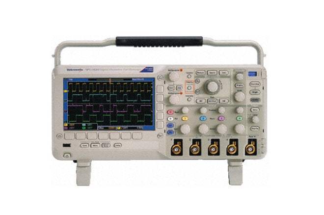
The Tektronix MSO2000 and DPO2000 Series are digital phosphor oscilloscopes (DPOs) built to visualize signals and find answers quickly. The DPO2000 Series provides 1 M points of usable record length on all channels, serial trigger and decode analysis options, and a variable low-pass filter, all in a compact form factor. The MSO2000 Series adds 16 integrated digital channels, allowing analog and digital signals to be visualized and time-correlated on a single instrument and extending triggering functionality across all 20 channels for debugging mixed analog and digital designs.
These oscilloscopes are applied to embedded design and debug, mixed signal design and debug, power measurements, automotive electronics, education and training, and video design and debug. Serial data analysis in embedded system design is among the most common applications that call for the series' long record length, as more embedded systems replace wide parallel buses with serial buses such as I2C, SPI, RS-232/422/485/UART, CAN, and LIN.
ValueTronics stocks and holds its own inventory in a 20,000 square foot secure warehouse at 1675 Cambridge Drive in Elgin, Illinois, where the company has specialized in test and measurement equipment since 1992. Every used unit is inspected and functionally verified in-house before it ships, while new units ship factory-sealed exactly as received from the manufacturer — so buyers get a condition-appropriate instrument backed by people who know the equipment.
Tektronix, founded in 1946, was acquired by Danaher Corporation in 2007 and became part of Fortive Corporation when Fortive was spun off from Danaher in 2016. The Tektronix brand has continued under its own name throughout these corporate transitions.
The MSO2000 and DPO2000 Series group six digital phosphor oscilloscopes into one family that shares a common platform: 1 GS/s sample rate, 1 M point record length on all channels, a 5,000 wfm/s waveform capture rate, Wave Inspector navigation and search, and the FilterVu variable low-pass filter. The DPO2000 models are digital phosphor oscilloscopes, while the MSO2000 models add 16 integrated digital channels for mixed-signal design and analysis.
Across the series, models differ in analog bandwidth and analog channel count, and the MSO variants extend triggering and analysis across as many as 20 time-correlated channels. Because the platform is shared, a measurement workflow learned on one model transfers directly to the others in the family.
Each model linked below is its own dedicated product page with condition-matched pricing for the pre-owned configuration you select. Compare bandwidth, analog channel count, and the mixed-signal option across the family, then choose the specific model and condition that fit your application.
The family splits along two axes. Analog bandwidth steps from 100 MHz on the MSO2012, MSO2014, DPO2012, and DPO2014 to 200 MHz on the MSO2024 and DPO2024. Analog channel count is 2 on the MSO2012 and DPO2012 and 4 on the MSO2014, MSO2024, DPO2014, and DPO2024.
The MSO designation adds 16 digital channels along with parallel bus trigger and analysis, which the DPO models do not include; all six models share the 1 GS/s sample rate and 1 M point record length. Refer to the comparison table below for the per-model bandwidth, channel-count, and calculated rise-time figures.
| Model | Bandwidth | Analog Channels | Digital Channels |
|---|---|---|---|
| DPO2024 | 200 MHz | 4 | 0 |
| MSO2012 | 100 MHz | 2 | 16 |
| MSO2014 | 100 MHz | 4 | 16 |
| MSO2024 | 200 MHz | 4 | 16 |
Additional differences in specifications beyond the few shown above are not listed here — see each model's full specifications below.
| Specification | Value |
|---|---|
| Horizontal System - Analog Channels | |
| Maximum Sample Rate (all channels) | 1 GS/s |
| Minimum Peak Detect Pulse Width | 3.5 ns |
| Maximum Record Length (all channels) | 1 M points |
| Maximum Duration of Time Captured at Highest Sample Rate (all channels) | 1 ms |
| Timebase Range | 2 ns to 100 s |
| Timebase Delay Time Range | -10 div to 5000 s |
| Channel-to-Channel Deskew Range | ± 100 ns |
| Timebase Accuracy | ± 25 ppm |
| Vertical System - Analog Channels | |
| Input Channels | 4 |
| Analog Bandwidth (-3 dB) | 200 MHz |
| Calculated Rise Time | 2.1 ns |
| Hardware Bandwidth Limits | 20 MHz |
| Input Coupling | AC, DC, GND |
| Input Impedance | 1 MΩ ± 2%, 11.5 pF ± 2 pF |
| Input Sensitivity Range | 2 mV/div to 5 V/div |
| Vertical Resolution | 8 bits |
| Max Input Voltage | 300 VRMS with peaks ≤450 V |
| DC Gain Accuracy (with offset set to 0 V) | ± 3% for 10 mV/div to 5 V/div, ± 4% for 2 mV/div to 5 mV/div |
| Offset Range (2 mV/div to 200 mV/div) | ± 1 V |
| Offset Range (>200 mV/div to 5 V/div) | ± 25 V |
| Channel-to-Channel Isolation (Any Two Channels at Equal Vertical Scale) | 100:1 at ≤200 MHz |
| Bandwidth at 2 mV/div (all models) | 20 MHz |
| Acquisition Modes | |
| Sample | Acquires sampled values. |
| Peak Detect | Captures glitches as narrow as 3.5 ns at all sweep speeds. |
| Averaging | From 2 to 512 waveforms included in average. |
| Roll | Scrolls waveforms right to left across screen at sweep speeds slower than or equal to 40 ms/div. |
| Trigger System | |
| Main Trigger Modes | Auto, Normal and Single. |
| Trigger Coupling | DC, HF reject (attenuates > 85 kHz), LF reject (attenuates < 65 kHz), noise reject (reduces sensitivity). |
| Trigger Holdoff Range | 20 ns to 8 s. |
| Trigger Signal Frequency Counter Resolution | 6 digits |
| Trigger Level Range (Any Channel) | ± 4.92 divisions from center of screen. |
| Trigger Level Range (External/auxiliary input) | ±6.25 V, 1x attenuation; ± 12.5 V, 10x attenuation. |
| Trigger Sensitivity (Internal DC Coupled) | |
| Analog Inputs | 0.4 division from DC to 50 MHz; 0.6 divisions >50 MHz to 100 MHz; 0.8 divisions >100 MHz to 200 MHz |
| External (Auxiliary Input) | 200 mV from DC to 100 MHz, 1x attenuation |
| Waveform Measurements | |
| Cursors | Waveform and Screen |
| Automatic Measurements | 29, of which up to four can be displayed on screen at any one time. |
| Waveform Math | Arithmetic — Add, subtract, and multiply waveforms. |
| Display Characteristics | |
| Display Type | 7 in (180 mm) liquid crystal TFT color display. |
| Display Resolution | 480 horizontal x 234 vertical pixels (WQVGA). |
| Waveform Styles | Vectors, Dots (In Video Trigger mode), Variable Persistence, Infinite Persistence. |
| Graticules | Full, Grid, Cross Hair, Frame. |
| Format | YT and XY. |
| Waveform Capture Rate | Up to 5,000 wfms/sec. |
| Input/Output Ports | |
| USB 2.0 High-Speed Host Port | Supports USB data storage devices and keyboards. |
| USB 2.0 High-Speed Device Port | Rear-panel port supports communication/control of oscilloscope by PC and all PictBridge compatible printers. |
| LAN Port | RJ-45 connector, supports 10/100Base-T (requires DPO2CONN). |
| GPIB | Adapt USB 2.0 device port to a GPIB port (requires TEK-USB-488). |
| Video Out Port | DB-15 female connector, connect to show the oscilloscope display on an external monitor or projector (requires DPO2CONN). |
| Auxiliary Input | Front-panel BNC connector. Input Impedance 1 MΩ ± 2%. Max input 300 VRMS with peaks ± 450 V. |
| Probe Compensator Output | Front-panel pins, Amplitude 5.0 V, Frequency 1 kHz. |
| Kensington Lock | Rear-panel security slot connects to standard Kensington style lock. |
| Power Source | |
| Power Source Voltage | 100 to 240 V ± 10%. |
| Power Source Frequency | 45 to 65 Hz (90 to 264 V), 360 to 440 Hz (100 to 132 V). |
| Power Consumption | 80 W maximum. |
| General Characteristics - Environmental | |
| Temperature (Operating) | 0 ºC to + 50 ºC. |
| Temperature (Nonoperating) | -40 ºC to + 71 ºC. |
| Humidity (Operating) | High: 30 ºC to 50 ºC, 5% to 60% Relative Humidity. Low: 0 ºC to 30 ºC, 5% to 95% Relative Humidity. |
| Altitude (Operating) | 3,000 meters (9,843 feet). |
| Altitude (Nonoperating) | 12,000 meters (39,370 feet). |
| Random Vibration (Operating) | 0.31 GRMS from 5 to 500 Hz, 10 minutes each axis, 3 axes, 30 minutes total. |
Important: Maximum input voltage (analog channels): 300 VRMS with peaks ≤ 450 V.
Important: Optional LAN/Ethernet (10/100Base-T) and Video Out connectivity is not built in: the LAN port and the Video Out (DB-15) port both require the DPO2CONN adapter, ordered separately.
Important: GPIB is not built in: adapting the rear-panel USB 2.0 device port to GPIB requires the TEK-USB-488 adapter, ordered separately.
Important: Direct attachment of TekVPI current probes requires the TekVPI External Power Supply (Tektronix part number 119-7465-xx), one per oscilloscope.
Important: Please specify power plug and manual version when ordering.
Important: Probes and accessories are not covered by the oscilloscope warranty and Service Offerings; refer to the datasheet of each probe and accessory model for its unique warranty and calibration terms.
Recommended pairing: add TekVPI active, differential, or current probes such as the TAP1500, TDP0500, or TCP0030 for automatic scaling and units through the TekVPI probe interface.
This pre-owned unit is inspected and functionally verified in-house before it ships and is backed by our pre-owned warranty. To confirm its exact condition, firmware revision, installed options, or included accessories for your application before ordering, contact our Test Architects.
ValueTronics supplies both new and used test and measurement equipment. New units ship factory-sealed, exactly as received from the manufacturer; every used unit is inspected and functionally verified in-house at our 20,000 sq ft secure facility in Elgin, Illinois before it ships. Our Test Architects can help you select the condition, calibration, and configuration that fit your application.
Please review the Manufacturer's Data Sheet to verify published specifications. Feedback on this webpage is always welcome — please reach out to your Test Architect at any time for questions or concerns. Thank you, we truly appreciate you being our customer.
Model No
Tektronix
Condition
Pre-Owned
Manufacturer
Tektronix
Osc_ch
4
Osc_freq
200 MHz
Osc_r
1 MΩ
Osc_sampl
1 GS/s

30+ Years in Business
Secure Payments
Sell Test Equipments
Knowledgeable Staff
On-site Lab
30+ Years in Business
Secure Payments
Sell Test Equipments
Knowledgeable Staff
On-site Lab
Request A Quote
 Chat Live
 Contact Us
 sales@valuetronics.com