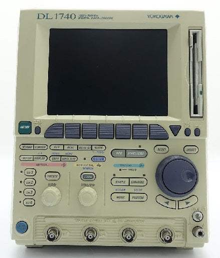
The Yokogawa DL1740 is a four-channel digital oscilloscope that pairs 500 MHz of analog bandwidth with deep acquisition memory in a compact, lightweight package built around an A4-size footprint and a weight of approximately 5.5 kg excluding options. Yokogawa positions it as a compact waveform-analysis instrument built around two stated design goals: easy and accurate capture of complex signals, and high-speed extraction and on-screen display of the information you want from large volumes of captured data. A newly developed DSE chip drives the fast screen updating that supports those goals.
The DL1740's measurement functions map to specific bench tasks. Its pulse-count function counts interrupt signals and pulse trains from sources such as stepping motors over a cursor-defined range. Envelope mode, which captures at the highest sampling rate regardless of the time-axis setting, is described as effective for observing high-frequency noise superimposed on a slow signal, while parameter computing supports real-time adjustment of gain. The GO/NO GO judgment function automatically discriminates waveforms against zones or parameter limits and can trigger actions such as outputting image data, saving waveform data, sounding a buzzer, or sending e-mail.
ValueTronics stocks and holds the DL1740 in our own 20,000-square-foot secure warehouse at 1675 Cambridge Drive in Elgin, Illinois. Every pre-owned unit is inspected and functionally verified in-house before it ships, while new units leave the warehouse factory-sealed exactly as received. Because we keep our own inventory on hand, we can match the right instrument and condition to your application and get it on its way quickly.
| Specification | Value |
|---|---|
| Basic Specifications | |
| Input coupling | AC-1 MΩ, DC-1 MΩ, DC-50 Ω, GND |
| Input impedance | 1 MΩ ±1.0%, 50 Ω ±1.0% |
| Voltage-axis sensitivity range (50-Ω input) | 2 mV—1 V/div (in 1, 2 or 5 mV increments) |
| Voltage-axis sensitivity range (1-MΩ input) | 2 mV—10 V/div (in 1, 2 or 5 mV increments) |
| Maximum input voltage (1-MΩ input, at 1 kHz or less frequencies) | 400 V (DC + AC peak)—282 Vrms CAT II |
| Maximum input voltage (50-Ω input) | 5 Vrms max. and 10 Vpeak max. |
| Frequency characteristics (50-Ω input) | 1 V—10 mV/div over 0 (DC) to 500 MHz, or 5 mV—2 mV/div over 0 (DC) to 400 MHz |
| Frequency characteristics (1-MΩ input, 700988 passive probe) | 10 V—10 mV/div over 0 (DC) to 400 MHz, or 5 mV—2 mV/div over 0 (DC) to 300 MHz |
| A/D conversion resolution | 8 bits (24 LSBs/div) |
| Maximum sampling rate (real-time, interleave on) | 1 GS/s |
| Maximum sampling rate (real-time, interleave off) | 500 MS/s |
| Maximum sampling rate (equivalent-time) | 100 GS/s |
| Maximum record length (interleave on) | 1 MW |
| Maximum record length (interleave off) | 500 KW |
| DC-mode accuracy | ±(1.5% of 8 divisions + voltage-axis offset accuracy) |
| Voltage-axis offset accuracy (2 mV—50 mV/div) | ±(1% of setpoint + 0.2 mV) |
| Voltage-axis offset accuracy (100 mV—500 mV/div) | ±(1% of setpoint + 2 mV) |
| Voltage-axis offset accuracy (1 V—10 V/div) | ±(1% of setpoint + 20 mV) |
| Sweep time (for 10-KW or longer record length) | 1 ns—50 s/div |
| Sweep time (for 1-KW record length) | 1 ns—5 s/div |
| Timebase accuracy | ±0.005% |
| External clock input | Within the 40 Hz—20 MHz input frequency range (for continuous clock signals only) |
| Trigger Block | |
| Trigger mode | AUTO, AUTO-LEVEL, NORMAL, SINGLE, SINGLE (N) |
| Trigger source | CH1 to CH4, LINE (commercial power source), EXT (EXT TRIG IN terminal) |
| Types of trigger | Edge, A→B (N), A Delay B, OR, Pattern, Pulse Width, TV |
| Display | |
| Screen updating rate (10-KW, all-points view mode) | 60 screens/s max. |
| Screen updating rate (1-MW, all-points view mode) | 30 screens/s max. |
| Display unit | 6.4-in. TFT color LCD |
| Functions — Vertical/Horizontal Axis Setting | |
| Input filter | Bandwidth can be limited to 100 MHz or 20 MHz for each of channels CH1 through CH4 separately. |
| Roll mode | 50 ms to 50 s/div (or 50 ms to 5 s/div for 1-KW record length only); enabled when trigger mode is Auto, Auto Level or Single |
| Acquisition mode | Normal, Averaging, Envelop, Box Average |
| Zoom | Zooms in on an on-screen waveform along the timebase (up to two areas, each with a different magnification) |
| X-Y display | Two waveform view modes—XY1 and XY2 |
| Analysis Functions | |
| Search and Zoom | Edge, Serial Pattern, Parallel Pattern, Pulse Width, Auto Scroll |
| History Search | Zone, Parameter |
| Cursor measurements | Marker, Horizontal, Vertical, Degree |
| Automatic waveform parameter measurement | P-P, Max, Min, High, Low, Avg, Rms, +OShot, -OShot, Sdev, Rise, Fall, Freq, Period, Duty, +Width, -Width, Int1TY, Int2TY, Int1XY, Int2XY, Pulse, Burst1, Burst2, AvgFreq, AvgPeriod |
| Statistical processing | Statistical data items: Min, Max, Avg, Cnt, Sdv; Statistics mode: Normal, Cycle, History |
| Computation | +, -, ¥, Binarization, Differentiation, Integration, Power Spectrum, Invert |
| GO/NO GO judgment | Executed by means of automatically measured waveform parameters and waveform zones |
| Image Data Output | |
| Built-in printer (optional) | Provides hardcopies of on-screen images using 112-mm wide print paper |
| External printer | Outputs image data through a USB interface or via Ethernet; supports Postscript, ESC/P, ESC/P2, LIPS3, PCL5 and BJ commands |
| Floppy/Zip®/SCSI-drive output data formats | Postscript, TIFF, BMP |
| Rear-panel I/O Block | |
| Communication interfaces | GP-IB, Keyboard/Printer ports (for USB keyboard/printer), USB (Ver. 1.0, for connection to personal computer), Ethernet (100BASE-TX and 10BASE-T, optional), SERIAL (RS-232, optional), SCSI (optional) |
| Signal I/Os | External trigger input/external clock input/trigger gate input, trigger output, RGB video signal output, GO/NO GO I/O |
| Probe power terminal (optional) | Number of outlets: 4; Output voltage: ±12 V |
| General Specifications | |
| Source voltage | 100 to 120 V AC / 220 to 240 V AC (switches automatically) |
| Power supply frequency | 50/60 Hz |
| Maximum power consumption | 200 VA |
| External dimensions | 220 (W) x 265.8 (H) x 264.1 (D) mm / 8.66 (W) x 10.46 (H) x 10.40 (D) inch |
| Weight | Approx. 6 kg (13.23 lbs; including the printer), or approx. 5.5 kg (12.13 lbs; excluding options) |
| Operating temperature range | 5—40°C |
Important: Maximum input voltage: 400 V (DC + AC peak), 282 Vrms CAT II on the 1 MΩ input; 5 Vrms and 10 Vpeak maximum on the 50 Ω input.
Important: Before operating the product, read the instruction manual thoroughly for proper and safe operation.
Important: If this product is for use with a system requiring safeguards that directly involve personnel safety, please contact the Yokogawa sales offices.
Important: When the interleave mode is on, the number of available channels reduces to half (2 channels); the 1 GS/s real-time sampling rate and 1 MW maximum record length apply only with interleave mode on.
Important: Ethernet interface (100BASE-TX and 10BASE-T) is available only on DL1740 units with the "/C10" option.
Recommended pairing: the 700939 FET probe and 700937 current probe draw power from the optional four-outlet ±12 V probe power terminal.
This pre-owned unit is inspected and functionally verified in-house before it ships and is backed by our pre-owned warranty. To confirm its exact condition, firmware revision, installed options, or included accessories for your application before ordering, contact our Test Architects.
ValueTronics supplies both new and used test and measurement equipment. New units ship factory-sealed, exactly as received from the manufacturer; every used unit is inspected and functionally verified in-house at our 20,000 sq ft secure facility in Elgin, Illinois before it ships. Our Test Architects can help you select the condition, calibration, and configuration that fit your application.
Please review the Manufacturer's Data Sheet to verify published specifications. Feedback on this webpage is always welcome — please reach out to your Test Architect at any time for questions or concerns. Thank you, we truly appreciate you being our customer.
Model No
Yokogawa
Condition
Pre-Owned
Manufacturer
Yokogawa
Osc_ch
4
Osc_freq
500 MHz
Osc_r
1 MΩ, 50 Ω
Osc_sampl
1 GS/s
B5
Built-in printer
C10
Ethernet interface
J1
Floppy drive

30+ Years in Business
Secure Payments
Sell Test Equipments
Knowledgeable Staff
On-site Lab
30+ Years in Business
Secure Payments
Sell Test Equipments
Knowledgeable Staff
On-site Lab
Request A Quote
 Chat Live
 Contact Us
 sales@valuetronics.com