The Kepco BOP Series is a family of bipolar operational power supply / amplifiers offered in 100 W, 200 W, and 400 W chassis configurations, with voltage ranges from ±20 V to ±200 V and current ranges from ±1 A to ±20 A. While each BOP is a fully rated DC power supply, it is also a high-powered operational amplifier with full four-quadrant bipolar operation — its output is capable of both sustained DC and the replication of arbitrary AC waveforms.
Kepco describes the BOP as suited to providing dynamically agile voltage for test and simulation. In Kepco's BOP, the voltage and current outputs can be controlled smoothly and linearly through the entire rated plus and minus ranges, passing smoothly through zero with no polarity switching. Because BOP units are high-speed power operational amplifiers rather than general-purpose power supplies, Kepco notes that the load characteristics should be mainly resistive to realize the full high-speed potential; capacitive loads above 0.1 microfarad require the BOP to be slowed via feedback capacitance to avoid oscillation, and special user-port terminals are provided to slow the BOP for optimum current-mode stability into inductive loading.
ValueTronics International stocks new and pre-owned Kepco BOP Series bipolar operational power supplies. Each unit moves through our 20,000-square-foot secure warehouse at 1675 Cambridge Drive, Elgin, Illinois, where it is logged, inspected, and prepared in-house before shipment — not drop-shipped from a third-party broker. Buyers working on four-quadrant test setups, magnetics drive, or arbitrary-waveform power applications can verify configuration details with our Test Architect team before purchase.
Kepco, Inc. has manufactured power supplies and power-conversion equipment continuously since 1946 from its Flushing, New York facility, and is certified to ISO 9001. The BOP product line has remained under Kepco branding throughout its history — there has been no corporate acquisition or rebrand of the Kepco T&M power-conversion business.
The Kepco BOP Series spans 100 W, 200 W, and 400 W chassis configurations across fourteen standard models. Within each power tier, models differ in voltage range (±20 V through ±200 V) and corresponding current range (±1 A through ±20 A), with voltage × current always matching the nominal power rating. Closed-loop voltage and current gains, output impedance characteristics, and dynamic response specifications vary across the family per the model table in the datasheet.
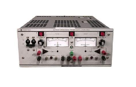
Two front-panel display options are offered family-wide: the M suffix denotes analog zero-center meters, while the D suffix denotes digital displays. Mechanical packaging is shared within each power tier — 100 W and 200 W models use a three-quarter-rack chassis, while 400 W models and the ±200 V / ±1 A BOP 200-1M use a full-rack chassis.
Each BOP model below is listed as its own dedicated product page with pre-owned-matched pricing and configuration detail. Select the model that matches your application's voltage range, current range, and power tier; suffix selection (M for analog meters, D for digital displays) and optional factory-installed digital interface cards are noted per the datasheet's suffix designations.
Differences across the family follow the model table directly. At the 100 W tier, the BOP 20-5M provides ±20 V at ±5 A; the BOP 50-2M provides ±50 V at ±2 A; the BOP 100-1M provides ±100 V at ±1 A. At the 200 W tier, six models cover ±20 V/±10 A through ±200 V/±1 A. At the 400 W tier, five models cover ±20 V/±20 A through ±100 V/±4 A.
Beyond voltage and current range, the per-model differences in the comparison table include closed-loop voltage gain (2.0 to 20.0 V/V), closed-loop current gain (0.1 to 2.0 A/V), voltage-mode series R and series L, current-mode shunt R and shunt C, and the dynamic specs (bandwidth, rise/fall time, large-signal frequency response, slewing rate, and step-load recovery in both voltage and current modes). The BOP 200-1M is noted as occupying the same chassis size as the 400 W models despite its 200 W rating, and Kepco notes its 200 V model uses FET output devices where the other models use transistors.
| Model | Output Voltage | Output Current | Output Power |
|---|---|---|---|
| BOP 20-10M | ± 20 V | ± 10 A | 200 W |
| BOP 20-5M | ± 20 V | ± 5 A | 100 W |
| BOP 20-5D | ± 20 V | ± 5 A | 100 W |
| BOP 50-2M | ± 50 V | ± 2 A | 100 W |
Additional differences in specifications beyond the few shown above are not listed here — see each model's full specifications below.
| Specification | Rating / Description | Condition |
|---|---|---|
| Input | ||
| a-c Voltage | 95-113, 105-125, 190-226, 210-250 V a-c | User selectable |
| Current | See source-current table | Max load, 115 V a-c |
| Frequency | 47-65 Hz | Range |
| Output | ||
| d-c Output | Bi-direction, series pass | Transistor (200 V model uses FET) |
| Type of Stabilizer | Automatic crossover | Voltage / current |
| Voltage | 0 to 100% of rating (bipolar) | Adjustment range for temp 0–55°C |
| Current | 0 to 100% of rating (bipolar) | Adjustment range for temp 0–55°C |
| Sink | See source/sink plot | Duty cycle |
| Error Sense | 0.5 V per load wire | Voltage allowance |
| Isolation Voltage | 500 V d-c or peak | Output to ground |
| Leakage Current | <5 microamperes | rms at 115 V a-c, 60 Hz |
| Output to Ground | <50 microamperes | p-p at 115 V a-c, 60 Hz |
| Series Connection | 500 V | Max voltage off ground |
| Parallel Connection | Current sharing | Use master-slave connection |
| OVP | Not available | — |
| Control | ||
| Type | Variable input, fixed gain | Voltage / current |
| Voltage / Current, Local | 10-turn zero-center pot | — |
| Remote Analog | -10 V to +10 V | — |
| Local Digital | Serial bus or GPIB or VXI | Optional internal BIT card |
| Remote Digital | Use SN or SNR interface | — |
| Bounding | ± Volt/current local (4 screwdriver trimmers); ± Volt/current remote 0 to 10 V | — |
| Dynamics | See dynamic spec table | Fast only |
| User Amplifiers | Uncommitted gain 20K | Two provided |
| References | ±10 V, 1 mA | Two provided |
| Mechanical | ||
| Input Connection | Detachable IEC type 3-wire | All models |
| Output Connections | Front signal/output binding posts; rear user port 50-terminal connector; rear output barrier strip | — |
| Meters | Two 2½" horizontal, 2% zero-center analog (M models) | Front panel |
| Indicators | Four LEDs | Voltage / Current / Bounding |
| Mounting (3/4 rack) | Use RA 37 rack adapter | 3/4 rack size |
| Mounting (full rack) | Mounting "ears" supplied | Full rack size |
| Cooling | Forced air | Exhaust to rear |
| Dimensions (3/4 rack) | 5-7/32" x 12-17/32" x 17-9/64" (132.6 x 318.3 x 435.4 mm) | H x W x D, add 2.5" rear for connector |
| Dimensions (Full rack) | 5-7/32" x 19" x 20-5/64" (132.6 x 482.6 x 510 mm) | H x W x D, add 2.5" rear for connector |
| Finish | Light gray, Fed Std 595 color 26440 | Front panel |
| Weight (100 W, 3/4 rack) | 47 lb (21.4 kg) | Packed for shipment |
| Weight (200 W, 3/4 rack) | 53 lb (24.1 kg) | Packed for shipment |
| Weight (Full rack / 400 W and BOP 200-1M) | 76 lb (34.5 kg) | Packed for shipment |
| Compliance | CE marked per Low Voltage Directive (LVD), EN61010-1 | — |
| Warranty | 5-Year Warranty | — |
| Influence Quantity | Voltage Mode Typical | Voltage Mode Maximum | Current Mode Typical | Current Mode Maximum | Preamplifier ΔEio | Preamplifier ΔIio | Reference ±10 V |
|---|---|---|---|---|---|---|---|
| Source (min.–max.) | <0.0005% | 0.001% | <0.002% | 0.005% | <5 µV | <1 nA | <0.0005% |
Please review the Manufacturer's Data Sheet to verify published specifications. Feedback on this webpage is always welcome — please reach out to your Test Architect at any time for questions or concerns. Thank you, we truly appreciate you being our customer.
Model No
Kepco
Condition
Used
Manufacturer
Kepco
Amps
10 A
Volts
20 V
Power
200 W

30+ Years in Business
Secure Payments
Sell Test Equipments
Knowledgeable Staff
On-site Lab
30+ Years in Business
Secure Payments
Sell Test Equipments
Knowledgeable Staff
On-site Lab
Request A Quote
 Chat Live
 Contact Us
 sales@valuetronics.com