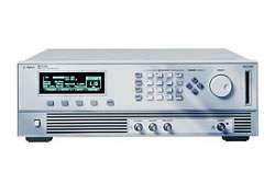
The Agilent 8114A is a 100 V / 2 A programmable pulse generator designed to deliver clean, reliable, and repeatable pulse waveforms for characterization and test applications. The instrument provides 100 Vpp output capability (2 A) into open circuit (or from a 1 kΩ source into 50 Ω), with a 15 MHz repetition rate, fixed 7 ns transitions, variable pulse width, and 3-digit resolution across all timing and level parameters.
This pulse generator is suited for characterization and test work where clean, accurate pulse waveforms are required, and where the device under test must be protected from accidental damage during setup and operation. Per the datasheet, the 8114A supports automated test system integration through SCPI programming commands, accepts external triggering and gating, and provides a TTL inhibit input that allows a feedback signal from the DUT or test system to hold the pulse output at its baseline level under hardware control.
ValueTronics International stores and tests pulse generators like the Agilent 8114A in our own 20,000 square foot secure warehouse at 1675 Cambridge Drive, Elgin, Illinois. Unlike drop-shippers and pass-through brokers, every instrument we list is physically present in our facility, where our technicians verify it against the manufacturer's published specifications before it leaves the dock. For a programmable pulse generator that customers depend on for repeatable timing accuracy and clean transitions, that hands-on verification is the difference between buying a model number and buying a confirmed working instrument.
The 8114A carries the Agilent brand from the period after Hewlett-Packard spun off its test and measurement business as Agilent Technologies in 1999. Agilent's electronic measurement business was subsequently transferred to Keysight Technologies in 2014, which is the current corporate successor for instruments in the 8114A's product family. Units in the field may be labeled HP, Agilent, or carry documentation referencing any of these successor entities.
| Specification | Value |
|---|---|
| Timing Characteristics | |
| Frequency range | 1 Hz to 15.00 MHz |
| Timing resolution (period, width) | 3 digits, 100 ps best case |
| RMS jitter (period, width, delay) | 0.03% ± 25 ps (± 0.05% ± 25 ps for period < 100 ns) |
| Period range | 66.7 ns to 999 ms |
| Period accuracy | ± 5% ± 100 ps |
| Width range | 10.0 ns to 150 ms (max: period − 10.0 ns) |
| Width accuracy | ± 5% ± 500 ps |
| Fixed delay | 42 ns typical (measured between Trigger Output and Output) |
| Additional variable delay range | 0.00 ns to 999 ms (max: period − 4 ns) |
| Delay accuracy | ± 5% ± 1 ns |
| Delay resolution | 3 digits, 10 ps best case |
| Transition time (10/90) | 50 Ω into 50 Ω: < 7 ns (amplitude > 5 V); High-Z into 50 Ω: < 12 ns (amplitude > 10 V) |
| Burst Count | 2 to 65536 (single or double pulses) |
| Duty cycle | 0.1% to 100% (subject to width and period specifications) |
| Level/Pulse Performance Characteristics | |
| Amplitude | 1.00 V to 50.0 V or 20.0 mA to 1.00 A (values approximately double for source or load resistance > 1 kΩ) |
| Amplitude accuracy | ± 1% of amplitude ± 100 mV |
| Amplitude resolution | 3 digits, best case 10 mV |
| Baseline (Standard Instrument) | < 100 mV + 0.5% of amplitude |
| Baseline (Option 001) | −25.0 V to 25.0 V (50 Ω source must be selected for variable baseline) |
| Baseline accuracy | ± 1% ± 100 mV ± 0.5% of amplitude |
| Pulse Window | ± 50 V |
| Base line noise | 10 mV RMS typical |
| Output connectors | BNC |
| Source Impedance | Selectable 50 Ω or High Impedance (> 1 kΩ) |
| Short circuit current | 2 A |
| Overshoot/preshoot/ringing | < ± 5% of amplitude ± 100 mV |
| Settling time | < 100 ns typical |
| Output Protection | Maximum external voltage 100 Vpp from 50 Ω source (±10 Vdc from 0 Ω source) |
| External Input | |
| Input impedance | 10 kΩ |
| Threshold | −10 V to +10 V with 100 mV resolution |
| Max. input voltage | ± 50 V |
| Sensitivity | ± 300 mVpp typical |
| Input transitions | < 100 ns |
| Frequency | dc to 15 MHz |
| Minimum pulsewidth | 10 ns typical |
| Trigger Output | |
| Level | Fixed TTL (2.5 V into 50 Ω) |
| Output impedance | 50 Ω typical |
| Trigger format | One pulse per period with 50% duty cycle typical |
| Max. external voltage | −2 V/+7 V |
| Transition times | 5 ns typical |
| Delay from external input to trigger output | 24 ns typical |
| Inhibit Input | |
| Input impedance | 100 kΩ |
| Threshold | 1.5 V (TTL) typical |
| Max. input voltage | ± 50 V |
| Input transitions | < 100 ns |
| Frequency | dc to 5 MHz |
| Minimum pulsewidth | 100 ns typical |
| Inhibit response time | 200 ns typical |
| Remote Control | |
| Standard | IEEE 488.2, 1987 and SCPI 1992.0 |
| Function Code | SH1, AH1, T6, L4, SR1, RL1, PP0, DC1, DT1, C0 |
| Programming time (one parameter or mode) | 5 to 20 ms typical |
| Programming time (recall setting) | 250 ms typical |
| General | |
| Operating temperature | 0°C to +55°C |
| Storage temperature | −40°C to +70°C |
| Humidity | 95% r.h. up to 40°C ambient temperature |
| EMC | EN 55011, Group 1, Class A |
| Noise emission | 5.5 bel typical |
| Safety | IEC1010 safety class 1 |
| Battery | Lithium CR2477-N |
| Power requirements | 100-240 Vac, ± 10%, 50-60 Hz; 100-120 Vac, ± 10%, 400 Hz |
| Power consumption | 500 VA max |
| Max. dimensions (H × W × D) | 133 mm × 426 mm × 422 mm |
| Weight | 14 kg net, 17 kg shipping |
| Recalibration period | One year recommended |
| Warranty | 1 year |
Please review the Manufacturer's Data Sheet to verify published specifications. Feedback on this webpage is always welcome — please reach out to your Test Architect at any time for questions or concerns. Thank you, we truly appreciate you being our customer.
Model No
Agilent
Condition
Used
Manufacturer
Agilent

30+ Years in Business
Secure Payments
Sell Test Equipments
Knowledgeable Staff
On-site Lab
30+ Years in Business
Secure Payments
Sell Test Equipments
Knowledgeable Staff
On-site Lab
Request A Quote
 Chat Live
 Contact Us
 sales@valuetronics.com