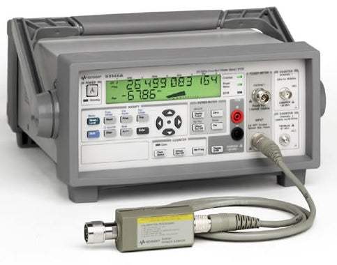
The Agilent 53140 Series combines a CW microwave counter, a true power meter, and a DC digital voltmeter into a single portable instrument. The series is offered in three models that differ by the upper frequency range of the microwave counter channel: the 53147A covers up to 20 GHz, the 53148A up to 26.5 GHz, and the 53149A up to 46 GHz. Each unit pairs the counter capability with a true power meter section compatible with the Agilent 8480 series of power sensors and a ±50 Vdc voltmeter section, all housed in a rugged chassis with rubber bumpers and a backlit LCD display.
According to the datasheet, the 53140 Series is positioned for the installation and maintenance of point-to-point microwave links — including cell-site to base-station links, business-to-business communication links, digital radio links along railroads, pipelines, or power lines, and satellite ground stations. The same instrument is also positioned for microwave component and assembly testing in automated test environments, where the three-in-one form factor reduces the rack space and capital required to assemble an equivalent measurement bench from separate counters, power meters, and voltmeters.
ValueTronics International has been supplying new and pre-owned test and measurement equipment to engineering, telecom, and field-service customers since 1992, and all inventory is stored, inspected, and tested in our own 20,000 square foot secure warehouse at 1675 Cambridge Drive, Elgin, Illinois. Rather than drop-shipping from third-party brokers, we evaluate each unit in-house against the manufacturer's published specifications, document its condition, and ship from our own stock — so the 53140 Series you receive has been verified by our technicians before it leaves the building.
The Agilent 53140 Series carries Hewlett-Packard test and measurement lineage. Hewlett-Packard spun off its test and measurement business as Agilent Technologies in 1999, and Agilent's electronic measurement division was subsequently established as Keysight Technologies in 2014. Instruments originally produced under the Agilent name during this era are part of the same engineering and product-support continuum that now operates under Keysight.
The 53140 Series is a three-model family that shares a common instrument architecture — CW microwave counter plus true power meter plus DC DVM in one chassis — and differs primarily in the upper frequency limit of the Channel 2 microwave counter input. All three models share the same Channel 1 range (10 Hz to 125 MHz), the same power meter section, the same DVM section, the same display, and the same programmable interfaces, so the comparison between them is fundamentally about how high in frequency the counter section needs to measure.
Because the rest of the instrument is common across the family, customers selecting between the 53147A, 53148A, and 53149A are essentially selecting a frequency ceiling — and accepting the corresponding differences in sensitivity at the upper end of each model's range and in the SWR profile of the Channel 2 input. The datasheet specifications support a side-by-side comparison on these axes.
Each pre-owned 53140 Series model below is listed on its own dedicated product page with condition-matched pricing and availability. Select the model that matches the frequency ceiling and connector configuration required by your application, then review that page for the current configuration we have on hand.
The 53147A is the 20 GHz model. Channel 2 sensitivity is specified at -33 dBm from 0.3 to 18 GHz and -29 dBm from 18 to 20 GHz, with a Channel 2 connector listed as SMA/APC-3.5 compatible female. The 53148A extends the upper range to 26.5 GHz, adding a -25 dBm sensitivity specification from 20 to 26.5 GHz while maintaining the same connector type. The 53149A extends the range further to 46 GHz, uses a 2.92 mm removable (SMA/APC-3.5 compatible) female connector on Channel 2, and specifies sensitivity of -23 dBm from 26.5 to 40 GHz and -17 dBm from 40 to 46 GHz.
Residual stability and acquisition time also vary across the family: residual stability on Channel 2 is specified at 0.6 LSD rms for the 53147A, 0.8 LSD rms for the 53148A, and 1.25 LSD rms for the 53149A. SWR above 20 GHz is specified at 3.0:1 for the 53148A through 26.5 GHz and 2.5:1 for the 53149A from 20 GHz through 46 GHz. The comparison table that follows lists the differing specifications side by side so the correct model can be matched to the application frequency.
| Model | Channel 2 Frequency Range | Channel 1 Frequency Range | Resolution |
|---|---|---|---|
| 53148A | 50 MHz to 26.5 GHz | 10 Hz to 125 MHz | 1 Hz to 1 MHz |
| 53147A | 50 MHz to 20 GHz | 10 Hz to 125 MHz | 1 Hz to 1 MHz |
| 53149A | 50 MHz to 46 GHz | 10 Hz to 125 MHz | 1 Hz to 1 MHz |
Additional differences in specifications beyond the few shown above are not listed here — see each model's full specifications below.
| Specification | 53148A |
|---|---|
| Counter Specifications | |
| Channel 1 Frequency Range (Normal) | 10 Hz to 125 MHz |
| Channel 1 Frequency Range (Low pass filter enabled) | 10 Hz to 50 kHz |
| Channel 2 Frequency Range | 50 MHz to 26.5 GHz |
| Channel 1 Sensitivity (10–30 Hz) | 40 mVrms |
| Channel 1 Sensitivity (30 Hz–125 MHz) | 25 mVrms |
| Channel 2 Sensitivity (50–300 MHz) | -20 dBm |
| Channel 2 Sensitivity (0.3–12.4 GHz) | -33 dBm |
| Channel 2 Sensitivity (12.4–18 GHz) | -33 dBm |
| Channel 2 Sensitivity (18–20 GHz) | -29 dBm |
| Channel 2 Sensitivity (20–26.5 GHz) | -25 dBm |
| Channel 1 Maximum Input | 2 Vrms |
| Channel 2 Maximum Input (50 MHz to 2 GHz) | +5 dBm |
| Channel 2 Maximum Input (2–46 GHz) | +13 dBm |
| Channel 1 Damage Level | 120 V (dc + ac pk) linearly derated to 5 Vrms at 125 MHz |
| Channel 2 Damage Level | +27 dBm |
| Channel 1 Impedance (nominal) | 1 MΩ/60 pF |
| Channel 2 Impedance (nominal) | 50 Ω |
| Channel 1 Connector | BNC female |
| Channel 2 Connector | SMA/APC-3.5 compatible female |
| Channel 2 SWR (50–300 MHz, typical) | 1.5:1 |
| Channel 2 SWR (0.3–10 GHz, typical) | 2.0:1 |
| Channel 2 SWR (10–20 GHz, typical) | 3.0:1 |
| Channel 2 SWR (20–26.5 GHz, typical) | 3.0:1 |
| Coupling (Ch 1 / Ch 2) | ac / ac |
| Channel 2 Emissions (typical, measuring/no input) | -40 dBm/<-70 dBm |
| Resolution Selection (Ch 1 and 2) | 1 Hz to 1 MHz |
| Accuracy | ±1 LSD ±residual stability ± (timebase error × frequency) |
| Channel 2 Residual Stability | 0.8 LSD rms |
| Channel 1 Measurement Time (typical) | 1/Resolution + 30 ms |
| Channel 2 Measurement Time (typical) | 1/Resolution + Acquisition time + 30 ms |
| Channel 2 Acquisition Time (FM Auto/FM Off) | 150 ms/125 ms |
| Channel 2 FM Tolerance (FM Auto) | 20 MHz p-p max at 10 MHz rate |
| Channel 2 FM Tolerance (FM Off) | 1 MHz p-p at 10 MHz rate |
| AM Tolerance (Ch 1 and 2) | Any index provided minimum signal level is not less than sensitivity |
| Channel 2 Amplitude Discrimination (>300 MHz) | Automatically measures the largest signal present provided signal is >10 dB (typical) above any signal separated by less than 75 MHz; >20 dB (typical) above any signal separated by more than 75 MHz |
Please review the Manufacturer's Data Sheet to verify published specifications. Feedback on this webpage is always welcome — please reach out to your Test Architect at any time for questions or concerns. Thank you, we truly appreciate you being our customer.
Model No
Agilent
Condition
Used
Manufacturer
Agilent

30+ Years in Business
Secure Payments
Sell Test Equipments
Knowledgeable Staff
On-site Lab
30+ Years in Business
Secure Payments
Sell Test Equipments
Knowledgeable Staff
On-site Lab
Request A Quote
 Chat Live
 Contact Us
 sales@valuetronics.com