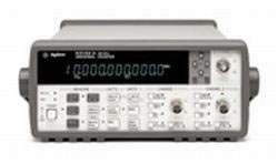
The Agilent 53131A is a two-channel universal frequency counter that delivers 225 MHz bandwidth and 10 digits per second of frequency and period resolution with a 1-second gate time. Time interval resolution is specified at 500 ps. Standard measurement functions include frequency, period, ratio, time interval, pulse width, rise/fall time, phase angle, duty cycle, totalize, and peak voltage, making it a broadly capable bench and systems counter.
The 53131A is built for both bench frequency measurements and computer-controlled systems applications. The intuitive user interface with one-button access to frequently used functions supports fast bench work, while the standard GPIB interface with full SCPI-compatible programmability and data transfer rates up to 200 fully formatted measurements per second supports automated test integration. Standard measurement functions cover the common stimulus-response and signal characterization tasks found in design, production test, and service environments.
ValueTronics has supplied new and used Agilent and Keysight test equipment to engineers, calibration labs, and production test groups for over three decades. Every unit moves through our 20,000 sq ft secure warehouse at 1675 Cambridge Drive, Elgin, Illinois, where it is received, inspected, and prepared by our in-house technical team before it ships. We are not a drop-shipper or a pass-through broker — the instruments we list are physically here, and the people you speak with have direct visibility into the inventory.
The 53131A was originally introduced by Hewlett-Packard, transferred to Agilent Technologies when HP spun off its test and measurement business in 1999, and then carried into Keysight Technologies when Agilent's electronic measurement group became Keysight in 2014. Counters bearing HP, Agilent, or Keysight branding in this family share the same product lineage and the same support ecosystem.
The 53131A, 53132A, and 53181A together form Agilent's high-performance counter family. All three share the same intuitive front-panel interface, the same real-time DSP measurement architecture, the same standard GPIB and RS-232 interfaces, the same IntuiLink software support, and the same range of optional oven timebases. They differ in measurement resolution, single-shot time interval resolution, channel configuration, and the breadth of measurement functions exposed.
Choosing among them is a question of measurement requirements. The 53131A and 53132A are full universal counters with two standard input channels and an optional third RF channel; they cover frequency, period, ratio, time interval, pulse width, rise/fall time, phase, duty cycle, totalize, and peak voltage. The 53181A is optimized as a single-channel RF counter measuring frequency, period, and peak voltage, with an optional second channel for higher-frequency inputs.
Each pre-owned counter listed below is its own product page with condition-matched pricing and configuration detail. The 53131A is the 10-digit/s universal counter; the 53132A is the higher-resolution 12-digit/s universal counter; and the 53181A is the single-channel RF counter. Use the per-model pages to confirm installed options, channel configuration, and timebase before ordering.
The 53131A occupies the standard-resolution position in the family: 10 digits per second of frequency and period resolution at 1-second gate time, 500 ps single-shot time interval resolution, and two standard input channels (Channel 1 and Channel 2) covering DC to 225 MHz. Frequency ratio measurements (Ch1/Ch2, Ch1/Ch3, Ch2/Ch1, Ch3/Ch1) and the full set of time-domain functions — pulse width, rise/fall time, phase, duty cycle, totalize — are standard. For most general-purpose frequency and time-interval work below the 12-digit resolution tier, the 53131A is the natural choice.
The 53131A and 53132A share an identical front-panel layout and the same standard measurement set. The 53132A adds two specific capabilities: 12 digits per second of frequency and period resolution (versus 10 digits on the 53131A), and 150 ps single-shot time interval resolution (versus 500 ps on the 53131A). The 53132A also supports advanced arming modes for time interval measurements, including the ability to use Channel 2 events to delay both Start and Stop Triggers, and is the only model in the family that accepts the Ultra-High Oven timebase (Option 012). Per-channel typical resolution is 200 ps on the 53132A versus 650 ps on the 53131A and 53181A.
The 53181A is structurally different from the universal counters. It is a single-channel RF counter measuring only frequency, period, and peak voltage, with an optional second channel offering 1.5 GHz, 3 GHz, 5 GHz, or 12.4 GHz coverage. It does not provide the time interval, pulse width, rise/fall time, phase, or duty cycle functions of the 53131A and 53132A. A digit-blanking function lets the operator eliminate unnecessary digits when reading measurements quickly, and a self-guided shallow menu structure simplifies front-panel use.
| Model | Resolution | Channels | Max Frequency (Std) |
|---|---|---|---|
| 53132A | 12 digits/s | 2 (optional Ch 3 up to 12.4 GHz) | 225 MHz |
| 53131A | 10 digits/s | 2 (optional Ch 3 up to 12.4 GHz) | 225 MHz |
| 53181A | 10 digits/s | 1 (optional Ch 2 up to 12.4 GHz) | 225 MHz |
Additional differences in specifications beyond the few shown above are not listed here — see each model's full specifications below.
| Specification | Value |
|---|---|
| Input Specifications — Channel 1 & 2 (53131A, 53132A) / Channel 1 (53181A) | |
| Frequency Range, dc Coupled | dc to 225 MHz |
| Frequency Range, ac Coupled | 1 MHz to 225 MHz (50 Ω); 30 Hz to 225 MHz (1 MΩ) |
| FM Tolerance | 25% |
| Voltage Range and Sensitivity (Sinusoid), dc to 100 MHz | 20 mVrms to ±5 V ac + dc |
| Voltage Range and Sensitivity (Sinusoid), 100 MHz to 200 MHz | 30 mVrms to ±5 V ac + dc |
| Voltage Range and Sensitivity (Sinusoid), 200 MHz to 225 MHz | 40 mVrms to ±5 V ac + dc |
| Single-Shot Pulse, 4.5 ns to 10 ns Pulse Width | 100 mVpp to 10 Vpp |
| Single-Shot Pulse, >10 ns Pulse Width | 50 mVpp to 10 Vpp |
| Trigger Level Range | ±5.125 V |
| Trigger Level Accuracy | ±(15 mV + 1% of trigger level) |
| Trigger Level Resolution | 5 mV |
| Damage Level, 50 Ω | 5 Vrms |
| Damage Level, 0 to 3.5 kHz, 1 MΩ | 350 Vdc + ac pk |
| Damage Level, >100 kHz, 1 MΩ | 5 Vrms |
| Impedance | 1 MΩ or 50 Ω |
| 1 MΩ Capacitance | 30 pF |
| Coupling | ac or dc |
| Low-Pass Filter | 100 kHz, switchable, -20 dB at >1 MHz |
| Input Sensitivity | Selectable between Low, Medium, or High (default) |
| Trigger Slope | Positive or Negative |
| Auto Trigger Level Range | 0 to 100% in 10% steps |
| Attenuator | x1 / x10 |
| Optional RF Channel (Ch 3 on 53131A/132A, Ch 2 on 53181A) | |
| Option 015 (53181A only) | 100 MHz to 1.5 GHz |
| Option 030 | 100 MHz to 3 GHz |
| Option 050 | 200 MHz to 5 GHz |
| Option 124 | 200 MHz to 12.4 GHz |
| Power Range, Option 030 (100 MHz to 2.7 GHz) | -27 dBm to +19 dBm |
| Power Range, Option 030 (2.7 GHz to 3 GHz) | -21 dBm to +13 dBm |
| Power Range, Option 050 | -23 dBm to +13 dBm (200 MHz to 5 GHz) |
| Power Range, Option 124 | -23 dBm to +13 dBm (200 MHz to 12.4 GHz) |
| Optional Channel Impedance | 50 Ω |
| Optional Channel Coupling | AC |
| Optional Channel VSWR | <2.5:1 |
| Measurement Specifications | |
| Frequency Range (Ch 1/2) | 0.1 Hz to 225 MHz |
| Period Range (Ch 1/2) | 4.44 ns to 10 s |
| Frequency Ratio Results Range | 10-10 to 1011 |
| "Auto" Gate Time (Ratio) | 100 ms |
| Time Interval Results Range (53131A, 53132A) | -1 ns to 105 s |
| Time Interval LSD (53131A) | 500 ps |
| Time Interval LSD (53132A) | 150 ps |
| Phase Results Range (53131A, 53132A) | -180° to +360° |
| Duty Cycle Results Range (53131A, 53132A) | 0 to 1 |
| Rise/Fall Time Results Range (53131A, 53132A) | 5 ns to 105 s |
| Pulse Width Results Range (53131A, 53132A) | 5 ns to 105 s |
| Totalize Results Range (53131A, 53132A) | 0 to 1015 |
| Totalize Resolution | ±1 count |
| Peak Volts Results Range | -5.1 V to +5.1 V |
| Peak Volts Resolution | 10 mV |
| Peak Volts Uncertainty (ac) | 25 mV + 10% of V |
| Peak Volts Uncertainty (dc) | 25 mV + 2% of V |
| Gate Time | Auto Mode, or 1 ms to 1000 s |
| Measurement Throughput (GPIB ASCII) | 200 measurements/s (maximum) |
| Time Base — Internal Stability | |
| Standard Temperature Stability (referenced to 25°C) | <5 x 10⁻⁶ |
| Option 001 (Medium Oven) Temperature Stability | <2 x 10⁻⁷ |
| Option 010 (High Oven) Temperature Stability | <2.5 x 10⁻⁹ |
| Option 012 (Ultra High Oven, 53132A only) Temperature Stability | <2.5 x 10⁻⁹ |
| Standard Aging Rate Per Month | <3 x 10⁻⁷ |
| Option 001 Aging Rate Per Day | <4 x 10⁻⁸ |
| Option 010 Aging Rate Per Day | <5 x 10⁻¹⁰ |
| Option 012 Aging Rate Per Day | <1 x 10⁻¹⁰ |
| External Arm Input | |
| Signal Input Range | TTL Compatible |
| Pulse Width | >50 ns |
| Transition Time | <250 ns |
| Impedance | 1 kΩ |
| Input Capacitance | 17 pF |
| Damage Level | 10 Vrms |
Please review the Manufacturer's Data Sheet to verify published specifications. Feedback on this webpage is always welcome — please reach out to your Test Architect at any time for questions or concerns. Thank you, we truly appreciate you being our customer.
Model No
Agilent
Condition
Used
Manufacturer
Agilent
Frequency
225 MHz
1
Medium-stability timebase
10
High-stability timebase
12
Ultra-high stability timebase (53132A only)
15
1.5 GHz RF input Ch 2 for 53181A only
30
3 GHz RF input Ch 3
50
5 GHz RF input with type N connector Ch 3
60
Rear-panel connectors
61
Moves 3.0 GHz Channel 3
62
Moves 5.0 GHz (Option 050) or 12.4 GHz
124
12.4 GHz RF input with type N connector Ch 3
BUY 3 GET 4TH FREE
BUY 3 UNITS GET THE 4TH FREE

30+ Years in Business
Secure Payments
Sell Test Equipments
Knowledgeable Staff
On-site Lab
30+ Years in Business
Secure Payments
Sell Test Equipments
Knowledgeable Staff
On-site Lab
Request A Quote
 Chat Live
 Contact Us
 sales@valuetronics.com