
🎓 Request a Quote To Get An EDU Discount
Couldn't load pickup availability
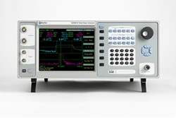
The Boonton 4500B RF Peak Power Analyzer is an instrument designed for capturing, displaying, analyzing, and characterizing RF power in both the time and statistical domains. The 4500B combines 100 psec timebase resolution with video bandwidth up to 65 MHz (sensor dependent), flexible triggering, and greater than 70 dB dynamic range (sensor dependent) without any range switching. The instrument operates with peak power sensors covering 1 MHz to 40 GHz with pulse measurement range of -50 to +20 dBm and modulated measurement range of -60 to +20 dBm.
Applications listed for the 4500B include pulsed RF such as RADAR, TDMA, and GSM; pseudorandom or noise-like signals such as CDMA and WLAN; and modulated time-slotted signals such as GSM-EDGE and TD-SCDMA. The instrument is also used for RF amplifier linearity testing, satcom, and avionics work. The optional statistical analysis package is positioned for characterizing noise-like RF such as CDMA, HDTV, and WLAN, with the ability to measure very infrequent power peaks across user-defined population sizes or acquisition intervals.
Boonton Electronics has operated as part of Wireless Telecom Group since the acquisition that brought the brand into the WTG family alongside Microlab and Noisecom. The 4500B is manufactured under the Boonton brand with Wireless Telecom Group corporate ownership.
The 4500B RF Peak Power Analyzer is configured at order through a series of option codes that determine channel count, input panel location, and analytical capabilities. The base 4500B is a single-channel instrument with front panel inputs, with options available to add a second channel, relocate inputs to the rear panel, add trigger outputs, add a rear-panel calibrator output, enable statistical analysis, add LAN remote control, substitute a removable flash drive for the internal hard drive, or extend the warranty.
Because configuration is set at order time through option selection rather than through distinct model variants, the comparison below reflects the available option codes documented in the datasheet's ordering information section.
Each pre-owned 4500B configuration listed below is its own dedicated product page with condition-matched pricing and availability. The option codes determine the hardware and software capabilities present in the specific unit.
The primary configuration choices are channel count (single or dual) and input panel location (front or rear). Dual-channel configurations enable simultaneous two-channel measurement and add a second external trigger input. Rear-panel input configurations are typically selected for rack-mounted system integration where front-panel access is not required.
The statistical analysis option (-10) adds gated CCDF and PDF capability for characterizing noise-like signals. The LAN option (-11) adds Ethernet remote control alongside the standard GPIB interface. The removable flash drive option (-15) substitutes for the internal hard drive and supports field-swappable storage. Trigger outputs (-06) and rear-panel calibrator output (-07) are added for system integration applications.
| Model | Channels | Input Location | Frequency Range |
|---|---|---|---|
| 4500B | Single | Front Panel | 1 MHz to 40 GHz |
| 4500B-01 | Dual | Front Panel | 1 MHz to 40 GHz |
| 4500B-02 | Single | Rear Panel | 1 MHz to 40 GHz |
| 4500B-03 | Dual | Rear Panel | 1 MHz to 40 GHz |
Additional differences in specifications beyond the few shown above are not listed here — see each model's full specifications below.
| Specification | Value |
|---|---|
| Sensor Inputs (specifications sensor model dependent) | |
| RF Frequency Range | 1 MHz to 40 GHz |
| Pulse Measurement Range | -50 to +20 dBm |
| Modulated Measurement Range | -60 to +20 dBm |
| Relative Offset Range | ±100.00 dB |
| Logarithmic Vertical Scale | 0.1 to 50 dBm/div in 1-2-5 sequence; 0.1 to 50 dBV/div in 1-2-5 sequence; 0.1 to 50 dBmV/div in 1-2-5 sequence; 0.1 to 50 dBuV/div in 1-2-5 sequence |
| Linear Vertical Scale | 1 nW/div to 50 MW/div in 1-2-5 sequence; 1 mV/div to 50 kV/div in 1-2-5 sequence |
| Video Bandwidth | 65 MHz |
| Rise Time | <7 nsec |
| Single-Shot Bandwidth | 5 MHz (based on 10 samples per pulse) |
| Pulse Repetition Rate | 50 MHz max |
| Minimum Pulse Width | 6 nsec |
| Time Base | |
| Time Base Range | 5 nsec/div to 1 hr/div |
| Time Base Accuracy | 0.01% |
| Time Base Resolution | 100 psec |
| Time Base Display | Sweeping or roll mode |
| Statistical X-Axis (optional) | |
| Scale | Linear or logarithmic, 1 to 7 cycles |
| Linear Ranges | 0.1%/div to 10%/div |
| Linear Offset | 0 to 99.9%, 0.1% resolution |
| Log Range | 1e-9% to 100% |
| Calibration Source | |
| Operating Modes | CW, internal or external pulse |
| Frequency | 1.024 GHz ± 0.01% |
| Level Range | -50 to +20 dBm |
| Resolution | 0.1 dB |
| Output VSWR | 1.20 maximum |
| Absolute Accuracy | ±0.065 dB (±1.5%) at 0 dBm |
| Accuracy vs Level | add ±0.03 dB per 5 dB increment from 0 dBm |
| Preset Internal Pulse Period | 0.1 or 1 or 10 msec |
| Preset Internal Pulse Duty Cycle | 10% to 90% in 10% increments |
| Variable Pulse On Time | 7 usec to 65.535 msec in 1 usec steps |
| Variable Pulse Period | 28 usec to 131.072 msec in 2 usec steps; Off-time limits within 7 usec to 65.535 msec |
| Pulse Polarity | + or − |
| RF Connector | Precision type N |
| External Pulse Input | Rear panel BNC, TTL level compatible |
| Measurement System | |
| Sensor Inputs | One or two sensor measurement channels |
| Measurement Technique | Random repetitive sampling system that provides pre and post trigger data as well as statistical histogram accumulation |
| Maximum Sampling Rate | 50 Mega-samples/second on up to four channels simultaneously (Equivalent effective sampling rate of 10 Giga-samples/second) |
| Memory Depth | 256K samples per channel at max sampling rate |
| Vertical Resolution | 14-bit A/D Converter |
| Waveform Averaging | 1 to 16,384 samples per data point (time domain measurement) |
| Number of Histogram Bins | 16,384 |
| Size of Sample Bins | 32-bits (4,000 mega-samples) |
| Bin Power Resolution | <0.02 dB |
| Statistical Acquisition (optional) | |
| Modes | Continuous or gated by pulse mode time markers |
| Sampling Rate | 25 Mega-samples/second on 2 channels simultaneously |
| Limit Count | Adjustable, 2–4096 Megasamples |
| Limit Time | 3600 seconds (appr. 2.5 min. at full sample rate) |
| Terminal Action | Stop, flush and restart or decimate performance |
| Trigger | |
| Trigger Source | Channel 1 (internal), Channel 2 (internal, with optional channel 2), External trigger 1, External trigger 2 (with optional channel 2) |
| Trigger Slope | + or − |
| Trigger Delay Range | 5 nsec to 500 nsec: -4 msec to +100 msec; 1 usec to 10 msec: ±4000 divisions; 20 msec to 3600 sec: -40 to +100 sec |
| Trigger Delay Resolution | 0.02 divisions |
| Trigger Hold-off Range | 0.0 – 1.0 sec |
| Trigger Hold-off Resolution | 10 nsec |
| Trigger Mode | Normal, auto, auto peak-to-peak, free Run |
| B Trigger Mode | A only, B delay-by-time, B delay-by-events specs |
| B Trigger Source | Chan 1, chan 2, ext trig 1, ext trig 2 |
| B Trigger Slope | + or − |
| B Trigger Events Counter Range | 1 to 999,999 events |
| B Trigger Time Delay Range | 0.0 – 1.0 sec |
| B Trigger Time Delay Resolution | 10 nsec |
| Internal Trigger Level Range | -40 to +20 dBm (sensor-dependent) |
| External Trigger Level Range | ±5 volts, ±50 volts |
| External Trigger Input | 1M or 50 ohm, DC Coupled |
| External Interfaces | |
| GPIB | Programmable interface; complies with SCPI ver. 1990 |
| RS-232C Interface 1 | Serial printer/plotter interface |
| RS-232C Interface 2 | Diagnostic interface |
| USB | General purpose i/o interface |
| LPT1 | Parallel printer/plotter (Centronics type) |
| LAN (optional) | Ethernet port |
Please review the Manufacturer's Data Sheet to verify published specifications. Feedback on this webpage is always welcome — please reach out to your Test Architect at any time for questions or concerns. Thank you, we truly appreciate you being our customer.
Model No
Boonton
Condition
Used
Manufacturer
Boonton

30+ Years in Business
Secure Payments
Sell Test Equipments
Knowledgeable Staff
On-site Lab
30+ Years in Business
Secure Payments
Sell Test Equipments
Knowledgeable Staff
On-site Lab
Request A Quote
 Chat Live
 Contact Us
 sales@valuetronics.com


