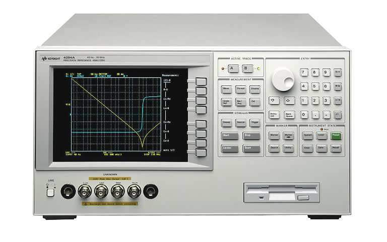
The Agilent 4294A Precision Impedance Analyzer characterizes passive components and materials from 40 Hz to 110 MHz using a four-terminal pair measurement configuration. The instrument resolves frequency to 1 mHz across the full span and measures impedance parameters including |Z|-θ, R-X, Ls-Rs, Ls-Q, Cs-Rs, Cs-Q, Cs-D, |Y|-θ, G-B, Lp-G, Lp-Q, Cp-G, Cp-Q, Cp-D, and complex Z-Y. Four BNC female connectors at the measurement port can be adapted to a 7 mm port using the 42942A Terminal Adapter or to a 3.5 mm port using the 42941A Impedance Probe.
Component engineers, materials researchers, and quality control teams use precision impedance analyzers to characterize capacitors, inductors, transformers, and other passive components across frequency — revealing self-resonance, parasitic behavior, equivalent series resistance, and dielectric response that single-frequency LCR meters cannot capture. The 4294A's swept measurement extends impedance characterization from the audio band through HF, supporting both R&D component design validation and incoming-inspection workflows where DC bias-dependent behavior must be verified.
Hewlett-Packard's test and measurement business was spun off as Agilent Technologies in 1999, and Agilent's electronic measurement division subsequently became Keysight Technologies in 2014. The 4294A traces its lineage through this corporate history; instruments carrying the Agilent brand on the front panel are the direct predecessors of current Keysight precision impedance products.
| Category | Specification | Value |
|---|---|---|
| Measurement Parameters | ||
| Impedance Parameters | Available | |Z|-θ, R-X, Ls-Rs, Ls-Q, Cs-Rs, Cs-Q, Cs-D, |Y|-θ, G-B, Lp-G, Lp-Q, Cp-G, Cp-Q, Cp-D, Complex Z-Y, |Z|-Ls, |Z|-Cs, |Z|-Lp, |Z|-Cp, |Z|-Rs, |Z|-Q, |Z|-D, Lp-Rp, Cp-Rp |
| Measurement Terminal Configuration | Type | Four-terminal pair configuration |
| Connector Type | Type | Four BNC (female) connectors. Can be converted to one port terminal using the Agilent 42942A Terminal Adapter (7-mm port) or 42941A Impedance Probe (3.5-mm port). |
| Source Characteristics — Frequency | ||
| Range | 40 Hz to 110 MHz | |
| Resolution | 1 mHz | |
| Accuracy (without Option 4294A-1D5) | ±20 ppm (at 23 ±5 °C); ±40 ppm (at 0 to 55 °C) | |
| Accuracy (with Option 4294A-1D5) | ±0.13 ppm (at 0 to 55 °C) | |
| Voltage Signal Level | ||
| Range | 5 mVrms to 1 Vrms | |
| Resolution | 1 mV | |
| Accuracy (4294A four-terminal pair or 42942A 7-mm port) | ±[(10 + 0.05 × f)% + 1 mV] (at 23 ±5 °C) | |
| Accuracy (42941A, 16048G/H measurement port) | ±[(15 + 0.1 × f)% + 1 mV] (at 23 ±5 °C) | |
| Current Signal Level | ||
| Range | 200 µArms to 20 mArms | |
| Resolution | 20 µA | |
| Output Impedance | ||
| Output impedance | 25 Ω (nominal) | |
| DC Bias Function | ||
| DC voltage bias range | 0 to ±40 V | |
| DC voltage bias resolution | 1 mV | |
| DC current bias range | 0 to ±100 mA | |
| DC current bias resolution | 40 µA | |
| Sweep Characteristics | ||
| Sweep parameters | Frequency, Signal voltage, Signal current, DC bias voltage, DC bias current | |
| Sweep type | Linear, Log, List, Zero-span, Manual | |
| Sweep direction | Up sweep, Down sweep | |
| Number of measurement points | 2 to 801 points | |
| List Sweep — number of segments | 1 to 18 | |
| Delay time range | 0 sec to 30 sec, 1 msec resolution | |
| Trigger Function | ||
| Trigger type | Continuous, Single, Number of groups | |
| Trigger source | Internal (Free run), External (BNC connector input), GPIB or LAN, Manual (Front key) | |
| Trigger event type | Point trigger, Sweep trigger | |
| Measurement Bandwidth / Averaging | ||
| Measurement bandwidth | 1 (Fast) to 5 (Precise), 5 steps | |
| Averaging type | Sweep-to-sweep averaging, Point averaging | |
| Averaging factor | 1 to 256 (integer) | |
| Calibration | ||
| User calibration | Calibration performed with user-defined calibration kit (OPEN, SHORT, LOAD) | |
| Port extension | Compensation when measurement terminal is extended from 7-mm (42942A) or 3.5-mm (42941A) connector | |
| Fixture compensation | OPEN, SHORT, LOAD at device contacts of test fixture | |
| Display | ||
| Size / Type | 8.4 inch color LCD (TFT) | |
| Number of pixels | 640 × 480 (VGA) | |
| Data / Memory traces | 2 data traces (A, B); 2 memory traces (A, B) | |
| Equivalent Circuit Analysis | ||
| Circuit model | 3 component model (4 models), 4 component model (1 model) | |
| Analysis type | Equivalent circuit parameters calculation, Frequency characteristics simulation | |
| Mass Storage | ||
| Flexible disk drive | 3.5 inch, Built-in, 1.44 MB, DOS format | |
| Volatile memory disk | 512 KB | |
| Non-volatile memory disk (Flash) | 10 MB | |
| Interfaces | ||
| GPIB | IEEE 488.1-1987, IEEE 488.2-1987, IEC 625, JIS C 1901-1987 | |
| LAN | 10 Base-T Ethertwist, RJ45 connector, TCP/IP, Telnet, FTP | |
| Printer Parallel Port | IEEE 1284 Centronics, HP PCL3, 25 pin D-SUB | |
| Keyboard | PS/2 style 101 English, Mini-DIN connector | |
| 8 Bit I/O Port | 15 pin D-SUB, TTL, 4 bit input / 8 bit output | |
| 24 Bit I/O Port (Handler Interface) | 36 pin D-SUB, TTL | |
| External Reference Input | 10 MHz ±10 ppm, –5 dBm to +5 dBm, 50 Ω, BNC (female) | |
| Internal Reference Output | 10 MHz, 0 dBm, 50 Ω, BNC (female) | |
| External Trigger Input | TTL, pulse width ≥2 µs, BNC (female) | |
| External Monitor Output | D-SUB 15 pin HD, 640 × 480 (VGA) | |
| Operating Conditions | ||
| Temperature (disk drive operating) | 10 °C to 40 °C | |
| Temperature (disk drive non-operating) | 0 °C to 40 °C | |
| Humidity (operating) | 15% to 80% RH (wet bulb ≤29 °C, no condensation) | |
| Altitude | 0 m to 2,000 m |
Please review the Manufacturer's Data Sheet to verify published specifications. Feedback on this webpage is always welcome — please reach out to your Test Architect at any time for questions or concerns. Thank you, we truly appreciate you being our customer.
Model No
Agilent
Condition
Used
Manufacturer
Agilent
1
DC Bias
2
Material Measurement Software
11
Delete High-Impedance Test Head
12
Low-Impedance Test Head
14
High-Temperature Low-Impedance Test Head
1C2
Add HP-IBASIC , HP-HIL Keyboard and Cable
1D5
High Stability Frequency Reference
800
STANDARD FREQUENCY REFERENCE
802
NO BOTTOM FEET
OIS
High-Temperature High-Impedance Test Head

30+ Years in Business
Secure Payments
Sell Test Equipments
Knowledgeable Staff
On-site Lab
30+ Years in Business
Secure Payments
Sell Test Equipments
Knowledgeable Staff
On-site Lab
Request A Quote
 Chat Live
 Contact Us
 sales@valuetronics.com