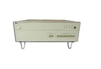
The Agilent 4083A DC/RF Parametric Test System is designed to perform fast and precise DC measurements, capacitance measurements, Flash cell test, high frequency applications such as ring oscillator measurement, and RF S-parameter and RFCV measurement. As a pre-owned parametric test platform from Valuetronics, the 4083A integrates DC sourcing and measurement, capacitance characterization, and RF measurement capability into a single test head with a fully guarded switching matrix that scales from 12 to 48 measurement pins plus a dedicated chuck connection.
The 4083A serves semiconductor process evaluation and parametric test applications including Flash cell test, ring oscillator measurement, RF S-parameter characterization, and RFCV measurement. It supports up to eight Source Monitor Units that can be individually configured to force either current or voltage while simultaneously measuring either current or voltage. The system can be constructed in either a low-current or an ultra low-current configuration depending on the matrix card specified, with only ultra low-current configurations supporting the High-Resolution SMU (HRSMU).
ValueTronics is a U.S.-based test and measurement specialist headquartered in our 20,000 sq ft secure warehouse at 1675 Cambridge Drive, Elgin, Illinois. Since 1992, we have built our reputation on professionally inspecting, testing, and grading every instrument before it leaves our facility — including complex parametric test platforms like the 4083A. Unlike drop-shippers or pass-through brokers, we hold inventory in-house, which means condition is verified by our technicians rather than described by a prior owner.
Hewlett-Packard's test and measurement business was spun out as Agilent Technologies in 1999. In 2014, Agilent's electronic measurement business was transferred to Keysight Technologies, while Agilent retained its life sciences and chemical analysis businesses. Instruments bearing the Agilent brand name in semiconductor parametric test, such as the 4083A, are part of this lineage.
| Specification | Value |
|---|---|
| General Description | |
| Supported SMUs | Up to 8 Source Monitor Units |
| Switching Matrix Pins | 12 to 48 DUT pins (configurable), plus one dedicated chuck connection pin |
| Matrix Card Types | Standard low-current or ultra low-current |
| RF Input Ports (Test Head) | 2 |
| RF Output Ports (Test Head) | Up to 10 |
| Ground Unit (GNDU) | 1, ±1.6 A |
| Switching Matrix Subsystem | |
| Maximum DUT Pins | 48 output pins plus one pin for prober chuck connection (triaxial connector) |
| SMU Ports in Testhead | 2 ports for low-current measurement (Non-Kelvin); 4 ports (Kelvin); 2 ports (Non-Kelvin); 1 port for GNDU (Kelvin) |
| Auxiliary (AUX) Ports | 6 for external instruments + 2 for HS-CMU or E4980A |
| Extended Paths | 48 (one on/off relay per path) |
| Optional High Frequency (HF) Ports | 6 |
| Maximum Voltage — SMU Port in Test Head | ±200 V |
| Maximum Voltage — AUX Ports 1 and 2 | ±200 V |
| Maximum Voltage — AUX Ports 3 to 8 | ±100 V |
| Maximum Voltage — Optional HF Ports | ±100 V (between force and common); ±100 V (between two of forces of all HF ports); ±100 V (between any HF port force and any extended path force) |
| Maximum Voltage — Extended Path | ±100 V |
| Zero Reference | ±200 mV |
| Maximum Current — SMU Port in Test Head | ±1.0 A |
| Maximum Current — GNDU | ±1.6 A |
| Maximum Current — AUX Port | ±1.0 A |
| Maximum Current — Optional HF Port | ±0.5 A |
| Maximum Current — Extended Path | ±0.5 A |
| Maximum Residual Resistance — Low Current Port | Force 1.0 Ω |
| Maximum Residual Resistance — Kelvin Port | Force 1.0 Ω, Sense 2.5 Ω |
| Maximum Residual Resistance — Non-Kelvin Port | Force 1.0 Ω |
| Maximum Residual Resistance — Optional HF Port | 2.0 Ω (supplemental) |
| Maximum Stray Capacitance between DUT Pins | 3 pF (supplemental) |
| Isolation Resistance — Low Current with Guard | 1×10¹⁵ Ω (supplemental) |
| Optional HF Port Bandwidth (@−3dB) | 60 MHz (50 Ω load, 3 × 24 configuration, supplemental) |
| Optional HF Port Cross Talk Between Pins | ±2% (5 kΩ load, 20 ns pulse transition time, supplemental) |
| Optional Pulse Switch | |
| Number of Blocks | 2 |
| Block 1 Switches | 3 relays (make or break, selectable) + 1 transfer-type relay |
| Block 2 Switches | 1 make-or-break relay + 2 transfer-type relays |
| Control Input Ports | One per block (PSC1, PSC2) |
| Maximum Voltage | ±40 V (between force and common of each switch) |
| Maximum Current | ±0.4 A (input to output) |
| Residual Resistance (IN to OUT) | Nominal 1.5 Ω (supplemental) |
| OFF Capacitance (IN to OUT) | 50 pF (Vin−Vout = 0 V, supplemental) |
| Operating Time of Switching | Max. 500 µs (supplemental) |
| DC Measurement — SMU Voltage | |
| SMU Types | HRSMU (High Resolution), MPSMU (Medium Power), HPSMU (High Power) |
| Voltage Range — MPSMU | ±2 V, ±20 V, ±40 V, ±100 V |
| Voltage Range — HPSMU | Up to ±200 V |
| Voltage Range — HRSMU | ±2 V, ±20 V, ±40 V, ±100 V |
| Voltage Force Resolution | 100 µV (±2 V range) to 10 mV (±200 V range) |
| Voltage Measure Resolution (Precision) | 2 µV (±2 V range) to 200 µV (±200 V range) |
| DC Measurement — SMU Current | |
| Current Range — HPSMU | 10 fA to 1 A |
| Current Range — MPSMU | 10 fA to 100 mA |
| Current Range — HRSMU | 1 fA to 100 mA |
| Maximum Capacitive Load | ≤1000 pF |
| Maximum Allowable Guard Capacitance | 250 pF (between signal line and guard line outside of matrix) |
| Maximum Slew Rate | 0.2 V/µs |
| Current Compliance Setting Range | 1 pA to maximum current |
| Ground Unit (GNDU) | |
| Output Voltage | 0 V |
| Maximum Current | ±1.6 A |
| Offset Voltage | ±200 µV |
| Maximum Capacitance Load | 1 µF (supplemental) |
| Digital Voltmeter (Agilent 3458A) | |
| Voltage Measurement Range — 0.1 V | Resolution 0.1 µV; Accuracy 0.01% + 100 µV |
| Voltage Measurement Range — 1 V | Resolution 1 µV; Accuracy 0.01% + 100 µV |
| Voltage Measurement Range — 10 V | Resolution 10 µV; Accuracy 0.01% + 200 µV |
| Voltage Measurement Range — 100 V | Resolution 100 µV; Accuracy 0.02% + 1 mV |
| Capacitance Measurement — High-Speed CMU | |
| Measurement Range (1 MHz) | 1 fF to 1.2 nF; 10 nS to 7.5 mS |
| Measurement Range (100 kHz) | 1 fF to 10 nF; 1 nS to 6.3 mS |
| Measurement Range (10 kHz) | 1 fF to 100 nF; 0.1 nS to 6.3 mS |
| Measurement Range (1 kHz) | 10 fF to 100 nF; 0.1 nS to 63 mS |
| Measurement Frequency | Setting range 1 kHz to 2 MHz (34 points) |
| Test Signal Level | 10 mV, 30 mV, 50 mV, 100 mV |
| DC Bias Full-Scale Voltage Range | ±10 V |
| DC Bias Setting Resolution | 1 mV |
| DC Bias Force Accuracy | ±(0.1% of setting + 10 mV) |
| Capacitance Measurement — Agilent E4980A LCR Meter | |
| Measurement Range (1 MHz) | 1 fF to 1.2 nF; 10 nS to 7.5 mS |
| Measurement Range (100 kHz) | 1 fF to 10 nF; 1 nS to 6.3 mS |
| Measurement Range (10 kHz) | 1 fF to 100 nF; 0.1 nS to 6.3 mS |
| Measurement Range (1 kHz) | 10 fF to 100 nF; 0.1 nS to 0.63 mS |
| Measurement Frequencies | 1 kHz, 10 kHz, 100 kHz, 1 MHz |
| DC Bias Voltage | ±40 V |
| DC Bias Force Accuracy (±40 V range) | 0.1% + 10 mV |
| Test Signal Level | 30 mV (rms) |
| Measurement Speed | MEDIUM or LONG |
| Optional Pulse Force Unit (HV-SPGU) | |
| Maximum Installable HV-SPGU Modules | 5 |
| Channels per HV-SPGU Module | 2 |
Please review the Manufacturer's Data Sheet to verify published specifications. Feedback on this webpage is always welcome — please reach out to your Test Architect at any time for questions or concerns. Thank you, we truly appreciate you being our customer.
Model No
Agilent
Condition
Used
Manufacturer
Agilent

30+ Years in Business
Secure Payments
Sell Test Equipments
Knowledgeable Staff
On-site Lab
30+ Years in Business
Secure Payments
Sell Test Equipments
Knowledgeable Staff
On-site Lab
Request A Quote
 Chat Live
 Contact Us
 sales@valuetronics.com