Request a Quote To Get An EDU Discount
Couldn't load pickup availability
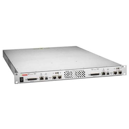
The Keithley 2606B System SourceMeter is a four-channel Source Measure Unit (SMU) instrument that consolidates the functions of a precision power supply, true current source, 6½-digit DMM, arbitrary waveform generator, and pulse generator into a single 1U full-rack chassis. Built on Keithley's third-generation SMU architecture, the 2606B delivers four 20-watt SMU channels in a tightly integrated source-and-measure package designed for demanding automated qualification and production-test environments.
The 2606B is positioned for I-V functional test and characterization across a wide range of devices. Per the datasheet, typical applications include optoelectronic devices such as VCSELs and laser diodes used in 3D sensing and telecommunications, high-brightness LEDs used in consumer products and automobiles, and displays. The datasheet also lists integrated devices including analog ICs, RFICs, ASICs, and system-on-a-chip (SOC) devices, along with discrete and passive components such as two-leaded sensors, disk drive heads, metal oxide varistors, diodes, zener diodes, capacitors, thermistors, and three-leaded BJTs and FETs. Simple ICs including optos, drivers, switches, sensors, converters, and regulators are also called out.
ValueTronics has supported automated test, semiconductor characterization, and optoelectronic-device test labs since 1992 from our 20,000 sq ft secure facility at 1675 Cambridge Drive, Elgin, Illinois. Every {{CONDITION}} 2606B chassis we ship is handled, inspected, and prepared in-house by our own technicians — not drop-shipped from a third party or routed through a broker. That direct chain of custody is what lets us stand behind condition descriptions, accessory completeness, and calibration documentation in a way that pass-through resellers structurally cannot.
Keithley Instruments was founded in Cleveland, Ohio in 1946 and built its reputation around precision low-level current and voltage measurement and source-measure unit technology. Keithley was acquired by Danaher Corporation in 2010 and, in 2016, moved with the broader test-and-measurement portfolio to Fortive Corporation when Fortive was spun off from Danaher. The Keithley brand and the System SourceMeter product line continue to operate under Tektronix, also a Fortive company, with Keithley-branded SMU instruments remaining the reference for I-V characterization in semiconductor and optoelectronic test.
| Specification | Value |
|---|---|
| DC Power | |
| Maximum output power per channel | 20.2 W maximum |
| Voltage source limits | 20.2 V at 1.0 A, −20.2 V at −1.0 A; 6.06 V at 3.0 A, −6.06 V at −3.0 A |
| Current source limits | 1.01 A at 20 V, −1.01 A at −20 V; 3.03 A at 6 V, −3.03 A at −6 V |
| Number of SMU channels | 4 |
| Voltage Source / Measure | |
| Voltage ranges | 100 mV, 1 V, 6 V, 20 V |
| Source programming resolution (best) | 5 µV (100 mV range) |
| Source accuracy (best) | ±(0.02% + 250 µV) on 100 mV range |
| Measure display resolution (best) | 100 nV (100 mV range) |
| Measure accuracy (best) | ±(0.015% + 150 µV) on 100 mV range |
| DCV basic accuracy | 0.015% |
| Current Source / Measure | |
| Current ranges | 100 nA, 1 µA, 10 µA, 100 µA, 1 mA, 10 mA, 100 mA, 1 A, 3 A |
| Source programming resolution (best) | 2 pA (100 nA range) |
| Source accuracy (best) | ±(0.06% + 100 pA) on 100 nA range |
| Measure display resolution (best) | 100 fA (100 nA range) |
| Measure accuracy (best) | ±(0.05% + 100 pA) on 100 nA range |
| Pulse | |
| Minimum programmable pulse width | 100 µs |
| Pulse width programming resolution | 1 µs |
| Pulse width programming accuracy | ±5 µs |
| Pulse width jitter | 2 µs |
| Additional Source Characteristics | |
| Noise (10 Hz to 20 MHz) | < 20 mV peak-peak, < 3 mV RMS, 6 V range |
| Transient response time | <70 µs to recover within 0.1% for 10% to 90% step change in load |
| Guard offset voltage | <4 mV, current <10 mA |
| Remote sense operating range | Max 3 V between HI and SENSE HI; Max 3 V between LO and SENSE LO |
| Additional Measurement Characteristics | |
| Input impedance | > 10 GΩ |
| Sense high input impedance | >10 GΩ |
| Maximum sense lead resistance | 1 kΩ for rated accuracy |
| Maximum load impedance | Normal mode 10 nF; High capacitance mode 50 µF |
| Common mode voltage | 250 VDC |
| Common mode isolation | >1 GΩ, < 4500 pF |
| Overrange | 101% of source range; 102% of measure range |
| Measurement Speed | |
| Maximum sweep rate (0.001 NPLC, Internal trigger) | Up to 20,000 readings/s (Measure to Memory, 60 Hz / 50 Hz) |
| Maximum single measurement rate (0.001 NPLC) | 1900 (1800) readings/s, Measure to USB |
| Maximum measurement range change rate | >7000/s for >10 µA; >2200/s when changing to/from a range ≥1 A |
| Command processing time | <1 ms |
| Triggering and Synchronization | |
| Trigger in to trigger out | 0.5 µs |
| Trigger in to source change | 10 µs |
| Trigger timer accuracy | ±2 µs |
| Source change after LXI trigger | 280 µs |
| Multi-node synchronized source change | < 0.5 µs |
| Single-node synchronized source change | < 0.5 µs |
| Programming / Memory | |
| Embedded scripting | Test Script Processor (TSP) |
| Minimum user memory available | 16 MB (approximately 250,000 lines of TSP code) |
| Buffer size (with timestamp and source setting) | >60,000 samples |
| Buffer size (without timestamp and source setting) | >140,000 samples |
| Timing | |
| Timer | Free-running 47-bit counter with 1 MHz clock input |
| Timestamp resolution | 1 µs |
| Timestamp accuracy | ±100 ppm |
| Digital I/O Interface | |
| Connector | 25-pin female D |
| Input/Output pins | 14 open drain I/O bits per module (up to 28 total) |
| Absolute maximum input voltage | 5.25 V |
| Absolute minimum input voltage | −0.25 V |
| Maximum logic low input voltage | 0.7 V, +850 µA max |
| Minimum logic high input voltage | 2.1 V, +570 µA |
| Maximum source current | +960 µA |
| Maximum sink current at max logic low (0.7 V) | −5.0 mA |
| Absolute maximum sink current | −11 mA |
| 5 V power supply pin | Limited to 250 mA, solid-state fuse protected |
| Interfaces & Expansion | |
| Ethernet | RJ-45 connector, LXI version 1.4 Core 2011, 10/100BaseT, Auto-MDIX |
| LXI compliance | LXI version 1.4 Core 2011 |
| Expansion interface | TSP-Link (Category 5e or higher LAN crossover cable, 9.84 ft / 3 m max between instruments) |
| TSP-Link nodes | Maximum of 32 nodes; each source-measure module uses one TSP-Link node |
| TSP-Link connectors | Four (two on each module) |
| USB Control | USB 2.0 Device: USB-TMC488 protocol |
| USB File System | USB 2.0 Host: Mass storage class device |
| General | |
| Power supply | 100 VAC to 240 VAC, 50 Hz or 60 Hz (auto sensing), 425 VA maximum |
| Cooling | Forced air; front and side intakes and rear exhaust |
| Warranty | 1 year |
| EMC | Conforms to European Union EMC Directive |
| Safety | NRTL Listed to UL61010-1, and CSA C22.2 No 61010-1; Conforms with European Union Low Voltage Directive |
| Environment | For indoor use only |
| Altitude | Maximum 6562 ft (2000 m) above sea level |
| Operating temperature/humidity | 0°C to 50°C, 70% relative humidity up to 35°C; derate 3% RH/°C, 35°C to 50°C |
| Storage temperature | −25°C to 65°C |
| Dimensions (Rack Mount) | 1.7 in. high × 19 in. wide × 26.8 in. deep (44 mm × 483 mm × 680 mm) |
| Weight | 13.6 kg (30 lb.) |
Please review the Manufacturer's Data Sheet to verify published specifications. Feedback on this webpage is always welcome — please reach out to your Test Architect at any time for questions or concerns. Thank you, we truly appreciate you being our customer.
Model No
Keithley
Condition
New
Manufacturer
Keithley
Volts
20 V
Volts
20 W
Amps
3 A

30+ Years in Business
Secure Payments
Sell Test Equipments
Knowledgeable Staff
On-site Lab
30+ Years in Business
Secure Payments
Sell Test Equipments
Knowledgeable Staff
On-site Lab
Request A Quote
 Chat Live
 Contact Us
 sales@valuetronics.com

