🎓 Request a Quote To Get An EDU Discount
Couldn't load pickup availability
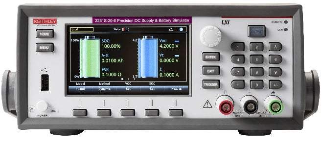
The Keithley 2281S-20-6 is a Series 2281S Battery Simulator and Precision DC Power Supply that integrates battery simulation with the functions of a high-precision linear-regulated DC power supply. The instrument can analyze the DC current consumption of a device under test, generate a battery model based on a battery charging process, and simulate a battery based on that model. Output ratings are 0 to 20 V, 0 to 6 A, and 120 W maximum, with current sinking capability up to 1 A.
Applications addressed in the datasheet center on battery-powered device development and testing. The battery simulator function allows engineers to simulate a real battery's output performance across its charge and discharge cycles, setting State of Charge (SOC) and open-circuit voltage (Voc) to any state in order to test a device-under-test's performance at various battery states. The battery test function performs charge/discharge testing on physical batteries, with charging current from 0 to 6 A and maximum discharging current of 1 A, automatically computing battery capacity in Amp-Hours and Equivalent Series Resistance (ESR) during the process. The instrument also functions as a standalone precision DC power supply for general bench and automated test work.
ValueTronics has stocked, tested, and shipped Keithley test and measurement instruments since 1992 from our 20,000 sq ft secure warehouse at 1675 Cambridge Drive in Elgin, Illinois. Every {{CONDITION}} Series 2281S unit is handled directly by our team in Elgin rather than passed through a third party — meaning the people who tested the instrument are the same people who can answer technical and condition-history questions about it. This direct ownership of the inventory, testing process, and shipping is the operational foundation behind every quote and condition report we issue.
Keithley Instruments was founded in 1946 in Cleveland, Ohio, and became part of Tektronix in 2010 when both companies were brought under Danaher Corporation. In 2016, Tektronix and Keithley moved to Fortive Corporation following Danaher's spin-off of its industrial businesses. The Series 2281S is sold today as a Keithley product within the Tektronix family of test and measurement brands.
| Specifications (23 °C ±5 °C with 1-hour instrument warm-up) | |
|---|---|
| DC Output Ratings | |
| Voltage | 0 to 20 V |
| Current | 0 to 6 A |
| Maximum Power | 120 W |
| Voltage — Source Setting | |
| Accuracy | ±(0.02% + 3 mV) |
| Resolution | 1 mV |
| Voltage — Measurement (0.5 V over-range) | |
| Accuracy | ±(0.02% + 2 mV) |
| Resolution | 0.1 mV |
| Additional Offset at Faster Measurement Settings (Voltage) | |
| 5½ (0.1 PLC) | 0.21 mV |
| 4½ (0.01 PLC) | 1.44 mV |
| 3½ (0.002 PLC) | 7.60 mV |
| Voltage Regulation | |
| Load | ±(0.01% + 2 mV) |
| Line | ±(0.01% + 1 mV) |
| Voltage Output Ripple and Noise | |
| Bandwidth 20 Hz–20 MHz | <1 mV RMS, <6 mV p-p |
| Load Transient Recovery Time | Resistive load change 50% to 100% or 100% to 50%: <50 µs to within 15 mV of V-set |
| Slew Rate | Rising and Falling: 10 V/s to 100 V/s. Up to 1000 V/s under limited conditions. 100 V/s default. |
| Maximum Source Voltage Drop per Lead | 1 V (to maintain specified voltage accuracy) |
| Maximum Sense HI and Sense LO Lead Resistance | 2 Ω (to maintain specified voltage accuracy) |
| Current — Current Limit Setting | |
| Full-scale Amps | 6.1 A |
| Accuracy | ±(0.05% + 5 mA) |
| Resolution | 0.1 mA |
| Current Measurement (120% over-range except 10 A) | |
| 10 mA range | Resolution 10 nA, Accuracy ±(0.04% + 10 µA) |
| 100 mA range | Resolution 100 nA, Accuracy ±(0.04% + 10 µA) |
| 1 A range | Resolution 1 µA, Accuracy ±(0.04% + 250 µA) |
| 10 A range | Resolution 10 µA, Accuracy ±(0.05% + 250 µA) |
| Current Pulse Measurement | |
| Minimum Pulse Width (10 mA and 100 mA range) | 2 ms |
| Minimum Pulse Width (1 A and 10 A range) | 140 µs |
| Minimum Time to Capture Two Consecutive Pulses | 0.5 ms |
| Current Regulation | |
| Load | ±(0.01% + 0.25 mA) |
| Line | ±(0.01% ± 0.25 mA) |
| Current Output Ripple and Noise | |
| Bandwidth 20 Hz–20 MHz | <3 mA RMS |
| Maximum Continuous Average Sink Current | |
| Non-programmable | 1.02 A ± 0.1 A (typical) |
| Battery Model Parameters | |
| Points in Simulation | 101 (0% State of Charge to 100% State of Charge) |
| Simulated ESR Range | 0 to 10 ohms |
| Simulated ESR Resolution | 1 milliohm |
| Simulated ESR Offset | −100 to 100 ohms |
| Simulated Voc Range | 0 to 20 Volts |
| Simulated Voc Resolution | 1 mV |
| Simulated Capacity Range | 1 mAh to 99 Ah |
| Simulated Capacity Resolution | 1 mAh |
| Other Timing Data | |
| CV to CC Transition Time (V-Set = 5 V, I-limit = 0.5 A, Resistive Load Change 25 Ω to 2.5 Ω) | 2.4 ms |
| CC to CV Transition Time (V-Set = 5 V, I-limit = 0.5 A, Resistive Load Change 2.5 Ω to 25 Ω) | 1.1 ms |
| Function Change | 10 ms (typical) |
| Output Off/On | 5 ms (typical) |
| Reverse Leads Actuation | >1.5 ms |
| Protection — Overvoltage (OVP) | |
| Setting Accuracy | ±(0.25% + 0.25 V) |
| Resolution | 125 mV |
| Response Time | <1.5 ms |
| Protection — Overcurrent (OCP) | |
| Setting Accuracy | ±(0.25% + 0.10 A) |
| Resolution | 25 mA |
| Response Time | <1.5 ms |
| Protection — Overtemperature (OTP) | |
| Output Turn-off Temperature | >93 °C (typical) |
| Response Time | <1.5 ms (typical) |
| General | |
| Common Mode Current | <6 µA peak-peak (typical) |
| Chassis Isolation | ±240 V, any terminal to chassis. >1 GΩ in parallel with <6.8 nF |
| Measurement Display Modes | Voltage and current, voltage only, current only |
| Measurement Acquisition Control | Continuous, manual, external digital input, PC bus |
| List Mode | Max 9 stored lists; 2–99 points per list; internal or USB storage |
| Memory Buffer | 2500 locations (voltage, current, CV/CC mode, time stamp); 9 memory slots for battery models; NVRAM |
| Display | 4.3 in. front panel color TFT, 480 × 272 pixels |
| Communications | |
| GPIB | IEEE-488.2 compliant |
| LAN | RJ-45 connector, 10/100BT, Auto MDIX; Static or DHCP; LXI Core 2011, version 1.4 |
| USB | USB2.0 device (rear, type B), USBTMC compliant; USB2.0 host (front, type A), full speed, supports U-disk drives |
| Input Connections | |
| Front | 2-wire, adjustable supporting safety shrouded banana, spade lug, or wire |
| Rear | 4-wire sense, 6-pin removable screw terminal, safety shrouded cover, removable local sense jumpers |
| Digital I/O | |
| Connector | 9-pin female D-sub, 6 Input/Output pins |
| Input Signal Levels | 0.7 V (max logic low), 3.7 V (min logic high) |
| Input Voltage Limits | −0.25 V (absolute min), +5.25 V (absolute max) |
| Maximum Source Current | +2.0 mA @ >2.7 V (per pin) |
| Maximum Sink Current | −50 mA @ 0.7 V (per pin, solid-state fuse protected) |
| Safety / Compliance | |
| EMC | Conforms to European Union EMC directive |
| U.S. NRTL Listing | UL61010-1 3rd ed 2012 |
| Canadian Certification | CAN/CSA C22.2 No. 61010-1 3rd ed 2012 |
| European Union Compliance | Low Voltage Directive, EN/IEC 61010-1 3rd ed 2010 |
| Power / Environment | |
| Cooling | Forced air, side intake, rear exhaust |
| Power Supply | 100 V / 120 V / 220 V / 240 V ±10% |
| Power Line Frequency | 50/60 Hz ±3 Hz, automatically sensed at power-on |
| Power Consumption | 630 VA peak |
Please review the Manufacturer's Data Sheet to verify published specifications. Feedback on this webpage is always welcome — please reach out to your Test Architect at any time for questions or concerns. Thank you, we truly appreciate you being our customer.
Model No
Keithley
Condition
New
Manufacturer
Keithley
Current
6 A
Voltage
20 V
Power
120 W

30+ Years in Business
Secure Payments
Sell Test Equipments
Knowledgeable Staff
On-site Lab
30+ Years in Business
Secure Payments
Sell Test Equipments
Knowledgeable Staff
On-site Lab
Request A Quote
 Chat Live
 Contact Us
 sales@valuetronics.com

