
🎓 Request a Quote To Get An EDU Discount
Couldn't load pickup availability
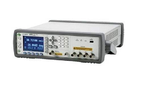
The Agilent E4980A is a precision LCR meter that measures impedance and related component parameters across a test frequency span of 20 Hz to 2 MHz. The E4980AL designation covers the low-frequency configurations of the same instrument — 20 Hz to 300 kHz, 500 kHz, or 1 MHz — and is used only for ordering and shipment; the unit itself is labeled E4980A. The instrument is fully compliant to the LXI Class C specification.
As an impedance measurement instrument, the E4980A characterizes capacitors, inductors, and resistive components by reporting parameters such as capacitance, inductance, resistance, reactance, impedance, admittance, conductance, susceptance, and dissipation or quality factor. Its built-in comparator sorts a primary parameter into nine bins plus out-of-bin and auxiliary categories, with a secondary parameter classified HIGH, IN, or LOW, supporting component sorting and pass/fail evaluation. A 201-point list sweep allows a sequence of measurement points to be evaluated automatically.
ValueTronics stocks this equipment directly from our own 20,000-square-foot secure warehouse at 1675 Cambridge Drive in Elgin, Illinois. Every pre-owned unit is inspected and functionally verified in-house before it ships, while new units leave factory-sealed exactly as received from the manufacturer. That combination of real inventory and hands-on verification is what distinguishes a ValueTronics purchase.
Agilent Technologies began as the test-and-measurement arm of Hewlett-Packard, which spun the business off as Agilent Technologies in 1999. In 2014, Agilent's electronic measurement business was established as Keysight Technologies, the brand under which this product line is supported today.
The E4980A and E4980AL share a single hardware platform built around precision four-terminal-pair impedance measurement. The E4980A is the full-range model covering 20 Hz to 2 MHz, while the E4980AL is the ordering designation applied to frequency-limited configurations — 20 Hz to 1 MHz, 500 kHz, or 300 kHz. Because the physical unit is labeled E4980A in every case, the family is best understood as one meter offered at several upper-frequency limits.
Across the family the core measurement parameters, four-terminal-pair terminals, compensation functions, and interface set remain common; the configurations differ chiefly in maximum test frequency and in which options can be installed.
Each configuration linked below is its own product page with pre-owned-matched pricing. Select the model whose frequency range and installed options match your application, and review that page's specifications and availability for the pre-owned unit you intend to order.
The E4980A, as the full 20 Hz to 2 MHz model, is the configuration that accepts the Power and DC Bias enhancement (Option 001), the bias current interface (Option 002), and the entry/standard model options — capabilities the frequency-limited configurations do not accept per the installable-options table.
The primary difference across the family is the upper test-frequency limit: 2 MHz for the E4980A, and 1 MHz, 500 kHz, or 300 kHz for the E4980AL frequency options 100, 050, and 030 respectively. The comparison table below lists each configuration's frequency range alongside its ordering and product model numbers.
Option availability also differs by configuration. The installable-options table shows that the Power and DC Bias enhancement, bias current interface, and entry/standard model options apply only to the 2 MHz model, while DC resistance measurement is supplied by default on the frequency-limited units. The handler and scanner interfaces are installable across all configurations.
| Model | Frequency Range | Basic Accuracy | Max Test Signal Voltage |
|---|---|---|---|
| E4980A | 20 Hz to 2 MHz | ±0.05% | 2 Vrms |
Additional differences in specifications beyond the few shown above are not listed here — see each model's full specifications below.
| Specification | Value |
|---|---|
| Measurement Functions | |
| Measurement parameters | Cp-D, Cp-Q, Cp-G, Cp-Rp; Cs-D, Cs-Q, Cs-Rs; Lp-D, Lp-Q, Lp-G, Lp-Rp, Lp-Rdc; Ls-D, Ls-Q, Ls-Rs, Ls-Rdc; R-X; Z-θd, Z-θr; G-B; Y-θd, Y-θr; Vdc-Idc |
| Equivalent circuits for measurement | Parallel, Series |
| Impedance range selection | Auto (auto range mode), manual (hold range mode) |
| Trigger mode | Internal trigger (INT), manual trigger (MAN), external trigger (EXT), GPIB trigger (BUS) |
| Measurement terminal | Four-terminal pair |
| Test cable length | 0 m, 1 m, 2 m, 4 m |
| Measurement time modes | Short mode, medium mode, long mode |
| Averaging | 1 - 256 measurements (resolution 1) |
| Trigger delay time | 0 s - 999 s; resolution 100 µs (0 s - 100 s), 1 ms (100 s - 999 s) |
| Step delay time | 0 s - 999 s; resolution 100 µs (0 s - 100 s), 1 ms (100 s - 999 s) |
| Test Signal — Frequency | |
| Test frequency range | 20 Hz - 2 MHz (standard); 20 Hz - 1 MHz (Option 100); 20 Hz - 500 kHz (Option 050); 20 Hz - 300 kHz (Option 030) |
| Resolution | 0.01 Hz (20 Hz - 99.99 Hz); 0.1 Hz (100 Hz - 999.9 Hz); 1 Hz (1 kHz - 9.999 kHz); 10 Hz (10 kHz - 99.99 kHz); 100 Hz (100 kHz - 999.9 kHz); 1 kHz (1 MHz - 2 MHz) |
| Measurement accuracy | ± 0.01% |
| Test Signal — Voltage (standard) | |
| Range | 0 Vrms - 2.0 Vrms |
| Resolution | 100 µVrms (0 - 0.2 Vrms); 200 µVrms (0.2 - 0.5 Vrms); 500 µVrms (0.5 - 1 Vrms); 1 mVrms (1 - 2 Vrms) |
| Accuracy, Normal | ±(10% + 1 mVrms) (test frequency ≤ 1 MHz: spec.; > 1 MHz: typ.) |
| Accuracy, Constant (ALC on) | ±(6% + 1 mVrms) (test frequency ≤ 1 MHz: spec.; > 1 MHz: typ.) |
| Test Signal — Current (standard) | |
| Range | 0 Arms - 20 mArms |
| Resolution | 1 µArms (0 - 2 mArms); 2 µArms (2 - 5 mArms); 5 µArms (5 - 10 mArms); 10 µArms (10 - 20 mArms) |
| Accuracy, Normal | ±(10% + 10 µArms) (test frequency ≤ 1 MHz: spec.; > 1 MHz: typ.) |
| Accuracy, Constant (ALC on) | ±(6% + 10 µArms) (test frequency ≤ 1 MHz: spec.; > 1 MHz: typ.) |
| Output impedance | 100 Ω (nominal) |
| Test Signal Level Monitor Accuracy | |
| Voltage monitor (Vac), 5 mVrms - 2 Vrms, ≤ 1 MHz | ± (3% of reading value + 0.5 mVrms) |
| Voltage monitor (Vac), 5 mVrms - 2 Vrms, > 1 MHz | ± (6% of reading value + 1 mVrms) |
| Current monitor (Iac), 50 µArms - 20 mArms, ≤ 1 MHz | ± (3% of reading value + 5 µArms) |
| Current monitor (Iac), 50 µArms - 20 mArms, > 1 MHz | ± (6% of reading value + 10 µArms) |
| Allowable Display Ranges | |
| Cs, Cp | ± 1.000000 aF to 999.9999 EF |
| Ls, Lp | ± 1.000000 aH to 999.9999 EH |
| D | ± 0.000001 to 9.999999 |
| Q | ± 0.01 to 99999.99 |
| R, Rs, Rp, X, Z, Rdc | ± 1.000000 aΩ to 999.9999 EΩ |
| G, B, Y | ± 1.000000 aS to 999.9999 ES |
| Vdc | ± 1.000000 aV to 999.9999 EV |
| Idc | ± 1.000000 aA to 999.9999 EA |
| θr | ± 1.000000 arad to 3.141593 rad |
| θd | ± 0.0001 deg to 180.0000 deg |
| Δ% | ± 0.0001 % to 999.9999 % |
| Basic Accuracy Ab — SHORT mode | |
| 20 - 125 Hz | (0.6%)×(50 mVrms/Vs) [5-50 mVrms]; 0.60% [50-300 mVrms]; 0.30% [0.3-1 Vrms]; 0.30% [1-10 Vrms]; 0.30% [10-20 Vrms] |
| 125 Hz - 1 MHz | (0.2%)×(50 mVrms/Vs) [5-50 mVrms]; 0.20% [50-300 mVrms]; 0.10% [0.3-1 Vrms]; 0.15% [1-10 Vrms]; 0.15% [10-20 Vrms] |
| 1 MHz - 2 MHz | (0.4%)×(50 mVrms/Vs) [5-50 mVrms]; 0.40% [50-300 mVrms]; 0.20% [0.3-1 Vrms]; 0.30% [1-10 Vrms]; 0.30% [10-20 Vrms] |
| Basic Accuracy Ab — MED, LONG mode | |
| 20 - 100 Hz | (0.25%)×(30 mVrms/Vs) [5-50 mVrms]; 0.25% [50-300 mVrms]; 0.10% [0.3-1 Vrms]; 0.15% [1-10 Vrms]; 0.15% [10-20 Vrms] |
| 100 Hz - 1 MHz | (0.1%)×(30 mVrms/Vs) [5-50 mVrms]; 0.10% [50-300 mVrms]; 0.05% [0.3-1 Vrms]; 0.10% [1-10 Vrms]; 0.15% [10-20 Vrms] |
| 1 MHz - 2 MHz | (0.2%)×(30 mVrms/Vs) [5-50 mVrms]; 0.20% [50-300 mVrms]; 0.10% [0.3-1 Vrms]; 0.20% [1-10 Vrms]; 0.30% [10-20 Vrms] |
| Temperature Factor Kt | |
| 0 - 18 °C | 4 |
| 18 - 28 °C | 1 |
| 28 - 55 °C | 4 |
| DC Bias Signal (standard) | |
| Test signal voltage range | 0 V to +2 V |
| Resolution | 0 V / 1.5 V / 2 V only |
| Accuracy (23 °C ± 5 °C) | 0.1% + 2 mV |
| Accuracy (0 to 18 °C or 28 to 55 °C) | (0.1% + 2 mV) × 4 |
| Output impedance | 100 Ω (nominal) |
| DC bias test signal current (1.5 V/2.0 V) | Output current: Max. 20 mA |
| Compensation Functions | |
| OPEN compensation | Compensates errors caused by the stray admittance (C, G) of the test fixture |
| SHORT compensation | Compensates errors caused by the residual impedance (L, R) of the test fixture |
| LOAD compensation | Compensates errors between the actual measured value and a known standard value under the measurement conditions desired by the user |
| List Sweep | |
| Points | Maximum of 201 points |
| First sweep parameter | Test frequency, test signal voltage, test signal current, test signal voltage of DC bias signal, test signal current of DC bias signal, DC source voltage |
| Second sweep parameter | None, impedance range, test frequency, test signal voltage, test signal current, test signal voltage of DC bias signal, test signal current of DC bias signal, DC source voltage |
| Trigger modes | Sequential mode, Step mode |
| Comparator Function | |
| Bin sort (primary) | 9 BINs, OUT_OF_BINS, AUX_BIN, and LOW_C_REJECT |
| Bin sort (secondary) | HIGH, IN, LOW |
| Sorting modes | Sequential mode, tolerance mode |
| General Specifications | |
| Rated voltage | 100 - 240 VAC |
| Power consumption | Max. 150 VA |
| Operating temperature | 0 - 55°C |
| Outer dimensions | 375 (width) x 105 (height) x 390 (depth) mm (nominal) |
| Weight | 5.3 kg (nominal) |
| Safety | IEC/EN 61010-1; INSTALLATION CATEGORY II, POLLUTION DEGREE 2, MEASUREMENT CATEGORY NONE; intended for indoor use |
| EMC | IEC 61326-1; CISPR 11 Group 1, Class A |
Important: Discharge capacitors before connecting them to the UNKNOWN terminal or a test fixture to avoid damage to the instrument.
Important: Front-panel UNKNOWN terminal maximum rating: 42 V Peak Max Output, 10 VDC Max, Measurement Category CAT I.
Important: Use the recommended USB memory device exclusively for the E4980A; otherwise previously saved data may be cleared. If a USB memory other than the recommended device is used, data may not be saved or recalled normally. Agilent Technologies will NOT be responsible for data loss in the USB memory caused by using the E4980A.
Recommended pairing: the Agilent 16047A/B/D/E test fixtures are the cable/fixture set referenced for the meter's specified four-terminal-pair measurements.
This pre-owned unit is inspected and functionally verified in-house before it ships and is backed by our pre-owned warranty. To confirm its exact condition, firmware revision, installed options, or included accessories for your application before ordering, contact our Test Architects.
ValueTronics supplies both new and used test and measurement equipment. New units ship factory-sealed, exactly as received from the manufacturer; every used unit is inspected and functionally verified in-house at our 20,000 sq ft secure facility in Elgin, Illinois before it ships. Our Test Architects can help you select the condition, calibration, and configuration that fit your application.
Please review the Manufacturer's Data Sheet to verify published specifications. Feedback on this webpage is always welcome — please reach out to your Test Architect at any time for questions or concerns. Thank you, we truly appreciate you being our customer.
Model No
Agilent
Condition
Pre-Owned
Manufacturer
Keysight Technologies
Lcr_met_freq
20 Hz to 2 MHz
16380C Agilent Standard Used
16380C
Keysight 3458A 8.5 Digit High-Performance Digital Multimeter (Pre-Owned)
3458A
16380A Agilent Standard Used
16380A
E4980AL Agilent LCR Meter Used
E4980AL
16451B Agilent Fixture Used
16451B
Agilent 16034G Test Fixture for Small SMD Components (2-Terminal, DC to 110 MHz) (Pre-Owned)
16034G
Agilent 16047E Test Fixture for Axial Lead Components (Pre-Owned)
16047E
Agilent 16034E Test Fixture for SMD Components (2-Terminal) for 4288A Capacitance Meter (Pre-Owned)
16034E
16089C Agilent Accessory Used
16089C
Agilent 16334A Tweezer-Type Test Fixture for SMD Components (2-Terminal, DC to 15 MHz) (Pre-Owned)
16334A
16089B Agilent Accessory Used
16089B
Agilent 16048E 3.8-Meter BNC Test Leads for 4263B LCR Meter (Pre-Owned)
16048E
16089A Agilent Accessory Used
16089A
16048A Agilent Accessory Used
16048A
Agilent 16047A Axial and Radial Test Fixture for 4263B LCR Meter (Pre-Owned)
16047A
Agilent 4083A DC/RF Parametric Test System (Pre-Owned)
4083A
Agilent E8362B PNA Series Network Analyzer for 4083A RF S-Parameter and RFCV Measurement (Pre-Owned)
E8362B

30+ Years in Business
Secure Payments
Sell Test Equipments
Knowledgeable Staff
On-site Lab
30+ Years in Business
Secure Payments
Sell Test Equipments
Knowledgeable Staff
On-site Lab
Request A Quote
 Chat Live
 Contact Us
 sales@valuetronics.com


