
🎓 Request a Quote To Get An EDU Discount
Couldn't load pickup availability
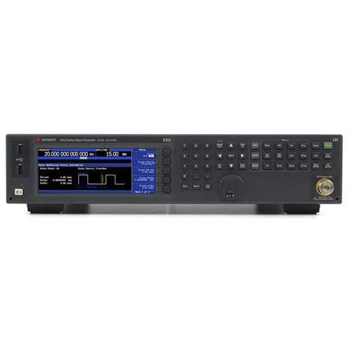
The N5173B is an EXG X-Series microwave analog signal generator from Agilent. It produces continuous-wave and swept microwave signals spanning 9 kHz at the low end up to 13, 20, 31.8, or 40 GHz at the top end, depending on the frequency option ordered (513, 520, 532, or 540). As an analog microwave source, it delivers a settable carrier with fine frequency resolution down to 0.001 Hz (nominal) and a phase offset adjustable in nominal 0.1-degree increments.
A signal generator supplies a known, controllable stimulus that engineers use to characterize how a device under test responds. The N5173B's simultaneous and composite modulation capabilities allow pulse, AM, and FM to run concurrently, which is useful for simulating signal impairments, FM chirp RADAR, or scan modulation. Its jitter performance is characterized against SONET/SDH data rates from 155 MB/s upward across the instrument's frequency range.
ValueTronics stocks and holds its own inventory in a 20,000 sq ft secure warehouse at 1675 Cambridge Drive, Elgin, Illinois, so the instruments we list are equipment we keep on hand rather than source on demand. Every used unit is inspected and functionally verified in-house by our technicians before it ships, while new units ship factory-sealed exactly as received from the manufacturer. That combination lets buyers choose between new and pre-owned with confidence that the condition described is the condition delivered.
Agilent Technologies originated as the test-and-measurement business of Hewlett-Packard, which was spun off as an independent company in 1999. In 2014, that electronic measurement business was transferred to Keysight Technologies. Datasheets bearing the Agilent name, such as this one, date from that intermediate era of the brand's history.
The N5173B is offered in four frequency configurations that share a common analog microwave architecture but differ in top-end reach: Option 513 covers 9 kHz to 13 GHz, Option 520 to 20 GHz, Option 532 to 31.8 GHz, and Option 540 to 40 GHz. Selecting the right option means matching the frequency ceiling to the highest signal your application needs to generate.
Across all four configurations the core feature set stays consistent: the same sweep modes, the same remote interfaces, the same OCXO reference architecture, and the same optional analog and pulse modulation suites. What scales with the option is the usable frequency span and a handful of frequency-dependent specifications.
Each pre-owned configuration linked below is its own dedicated product page with condition-matched pricing. Choose the frequency option that fits your application, then select the pre-owned listing that matches your budget and availability requirements.
Beyond the frequency ceiling, the configurations diverge in their RF output connector. Options 513 and 520 use a 3.5 mm (APC-3.5) SMA male connector, while Options 532 and 540 use a precision 2.4 mm male connector with supplied 2.4-to-2.4 mm and 2.4-to-2.9 mm female adapters. Option 1ED can add a Type-N connector to a 513 or 520.
Maximum specified output power and several spectral-purity figures also shift across the bands. For example, standard maximum output power and phase-noise values differ between the 513/520 and 532/540 groups and across frequency ranges, as detailed in the comparison table below.
| Model | Frequency Range | Max Output Power (Std) | Output Connector |
|---|---|---|---|
| N5173B | 9 kHz to 13 GHz | +18 dBm | 3.5 mm SMA male |
Additional differences in specifications beyond the few shown above are not listed here — see each model's full specifications below.
| Specification | Value |
|---|---|
| Frequency Range | |
| Frequency range (Option 513) | 9 kHz to 13 GHz |
| Frequency range (Option 520) | 9 kHz to 20 GHz |
| Frequency range (Option 532) | 9 kHz to 31.8 GHz |
| Frequency range (Option 540) | 9 kHz to 40 GHz |
| Resolution | 0.001 Hz (nom) |
| Phase offset | Adjustable in nominal 0.1° increments |
| Frequency Switching Speed — CW Mode (SCPI mode) | |
| Standard | ≤ 5 ms |
| Option UNZ | ≤ 1.15 ms (≤ 750 µs typ) |
| Option UZ2 | < 1.65 ms (1 ms typ) |
| Frequency Switching Speed — List/Step Sweep Mode (SCPI mode) | |
| Standard | ≤ 5 ms |
| Option UNZ | ≤ 900 µs (≤ 600 µs typ) |
| Option UZ2 | < 1.4 ms (850 µs typ) |
| Frequency Reference | |
| Internal time base reference oscillator aging rate | < ± 1 x 10^-7/year (nom); < ± 5 x 10^-10/day after 30 days (nom) |
| Initial achievable calibration accuracy | ± 4 x 10^-8 or ± 40 ppb |
| Adjustment resolution | < 1 x 10^-10 (nom) |
| Temperature effects | < ± 2 x 10^-8 from 20 to 30 °C (nom) |
| Line voltage effects | < ± 1 x 10^-9 for ± 10% change (nom) |
| Reference output frequency | 10 MHz |
| Reference output amplitude | ≥ +4 dBm (nom) into 50 Ω load |
| External reference input frequency standard | 10 MHz |
| External reference input frequency (Option 1ER) | 1 to 50 MHz (in multiples of 0.1 Hz) |
| Lock range | ± 1 ppm (nom) |
| External reference amplitude | 5 dBm ± 2 dB (nom) |
| External reference impedance | 50 Ω (nom) |
| External reference waveform | Sine or square |
| Sweep Modes (Frequency and Amplitude) | |
| Operating modes | Step sweep (equally spaced frequency and amplitude or logarithmically spaced frequency steps); List sweep (arbitrary list of frequency and amplitude steps) |
| Sweep range | Within instrument frequency range |
| Dwell time | 100 µs to 100 s |
| Number of points | 2 to 65535 (step sweep); 1 to 3201 (list sweep) |
| Step change | Linear or logarithmic |
| Triggering | Free run, trigger key, external, timer, bus (GPIB, LAN, USB) |
| Amplitude — Output Parameters | |
| Settable range (with Option 1E1 and 1EA) | +30 to –130 dBm |
| Settable range (without Option 1E1 and 1EA) | +19 to –20 dBm |
| Resolution | 0.01 dB (nom) |
| Step attenuator (Option 1E1) | 0 to 115 dB in 10 dB steps, mechanical type |
| Attenuator hold range | –15 dBm to maximum specified output power with step attenuator in 0 dB state; can be offset using Option 1E1 mechanical attenuator |
| Connector | 513/520 = 3.5 mm SMA male, 532/540 = 2.4 mm male, 50 Ω (nom); Option 1ED adds Type-N connector to a 513 or 520 |
| Maximum Output Power (dBm) — Option 513/520 | |
| 9 kHz to 3.2 GHz | +18 (Standard); +23 (High power Option 1EA) |
| > 3.2 to 13 GHz | +18 (Standard); +20 (Option 1EA) |
| > 13 to 20 GHz | +15 (Standard); +19 (Option 1EA) |
| Maximum Output Power (dBm) — Option 532/540 | |
| 9 kHz to 3.2 GHz | +14 (Standard); +21 (Option 1EA) |
| > 3.2 to 17 GHz | +14 (Standard); +16 (Option 1EA) |
| > 17 to 31.8 GHz | +13 (Standard); +15 (Option 1EA) |
| > 31.8 to 40 GHz | +11 (Standard); +15 (Option 1EA) |
| Absolute Level Accuracy in CW Mode (ALC on) — columns: Max power to +10 / <+10 to –10 / <–10 to –20 / <–20 to –75 / <–75 to –90 / <–90 to –120 dBm | |
| 9 kHz to 2 GHz | ± 0.6 / ± 0.6 / ± 0.7 / ± 0.7 / ± 1.4 (± 0.3 typ) dB |
| > 2 to 20 GHz | ± 0.9 / ± 0.7 / ± 0.7 / ± 0.7 / ± 1.6 (± 0.3 typ) dB |
| > 20 to 40 GHz | ± 0.9 / ± 0.8 / ± 1.1 / ± 1.1 / ± 2.0 dB |
| SWR (measured, CW Mode) | |
| ≤ 2 GHz | < 1.7:1 (0 dB attenuator); < 1.2:1 (5 dB and greater) |
| > 2 to 8 GHz | < 1.4:1 (0 dB); < 1.4:1 (5 dB and greater) |
| > 8 to 13 GHz | < 1.6:1 (0 dB); < 1.5:1 (5 dB and greater) |
| > 13 to 20 GHz | < 1.8:1 (0 dB); < 1.7:1 (5 dB and greater) |
| > 20 to 40 GHz | < 1.6:1 (0 dB); < 1.4:1 (5 dB and greater) |
| Amplitude — Leveling and Switching | |
| External detector leveling range | –0.2 mV to –0.5 V (nom) |
| External detector leveling bandwidth | 10 kHz (typ) |
| Amplitude switching speed (SCPI mode) | ≤ 2 ms (typ) |
| Power search (SCPI mode) | < 12 ms (meas) |
| Amplitude switching speed (List/step sweep mode) | ≤ 2 ms (typ) |
| User flatness correction — number of points | 3201 |
| User flatness correction — number of tables | Dependent on available free memory in instrument; 10,000 maximum |
| Standard Absolute SSB Phase Noise (dBc/Hz, CW) at 20 kHz Offset — () = measured | |
| 5 to < 250 MHz | –115 (–120) |
| 250 MHz | –129 (–134) |
| 500 MHz | –124 (–128) |
| 1 GHz | –118 (–122) |
| 2 GHz | –111 (–116) |
| 3 GHz | –105 (–110) |
| 4 GHz | –104 (–110) |
| 6 GHz | –99 (–104) |
| 10 GHz | –97 (–101) |
| 20 GHz | –90 (–95) |
| 40 GHz | –84 (–91) |
Important: Maximum reverse power at the RF output: 0.5 W, 0 Vdc.
Important: Analog modulation is not standard: AM, FM, and phase modulation require Option UNT; pulse modulation requires Option UNW (or UW2). The internal analog modulation source and multifunction generator (Option 303) also require Option UNT.
Important: Option 1ED (Type-N connector) is available only on Option 513 or 520 units; for instruments with Type-N connectors, specifications are degraded typically 0.2 dB above 18 GHz.
Important: Specifications represent warranted performance of a calibrated instrument stored for a minimum of 2 hours within the operating temperature range of 0 to 55 °C and after a 45 minute warm-up period.
Usage tip: the front- and rear-panel USB ports work with U2000 Series USB average power sensors, which also support the instrument's USB/LAN direct power-meter control for user flatness correction.
This pre-owned unit is inspected and functionally verified in-house before it ships and is backed by our pre-owned warranty. To confirm its exact condition, firmware revision, installed options, or included accessories for your application before ordering, contact our Test Architects.
ValueTronics supplies both new and used test and measurement equipment. New units ship factory-sealed, exactly as received from the manufacturer; every used unit is inspected and functionally verified in-house at our 20,000 sq ft secure facility in Elgin, Illinois before it ships. Our Test Architects can help you select the condition, calibration, and configuration that fit your application.
Please review the Manufacturer's Data Sheet to verify published specifications. Feedback on this webpage is always welcome — please reach out to your Test Architect at any time for questions or concerns. Thank you, we truly appreciate you being our customer.
Model No
Agilent
Condition
Pre-Owned
Manufacturer
Keysight Technologies
Rf_gen_freq
9 kHz to 13 GHz
Agilent E8257D PSG Analog Signal Generator (Pre-Owned)
E8257D
Agilent N5181B MXG X-Series Analog Signal Generator, 9 kHz to 3 or 6 GHz (Pre-Owned)
N5181B
Agilent E8267D PSG Vector Signal Generator (Pre-Owned)
E8267D
Agilent N5171B EXG X-Series Analog Signal Generator (Pre-Owned)
N5171B
Agilent N5172B EXG X-Series Vector Signal Generator (Pre-Owned)
N5172B
Agilent N5182B MXG X-Series Vector Signal Generator, 9 kHz to 3 or 6 GHz (Pre-Owned)
N5182B
Agilent N9310A 3 GHz RF Signal Generator (Pre-Owned)
N9310A
E8663D Agilent RF Generator Used
E8663D
N5106A Agilent Generator Used
N5106A
N5183B Keysight Agilent - Microwave Analog Signal Generator - Used
N5183B
N5191A Agilent Generator Used
N5191A
N5193A Agilent RF Generator Used
N5193A

30+ Years in Business
Secure Payments
Sell Test Equipments
Knowledgeable Staff
On-site Lab
30+ Years in Business
Secure Payments
Sell Test Equipments
Knowledgeable Staff
On-site Lab
Request A Quote
 Chat Live
 Contact Us
 sales@valuetronics.com


