Chat Live
 Contact Us
 sales@valuetronics.com


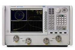
The Agilent N5227A is a PNA microwave network analyzer covering a frequency range of 10 MHz to 67 GHz, available in 2-port and 4-port configurations. It uses 1.85 mm (male), 50 ohm test port connectors and provides 1 Hz frequency resolution with +/-1 ppm frequency accuracy. Typical performance information is provided between 67 GHz and 70 GHz, where performance is degraded at particular frequencies due to the modes of the 1.85 mm connectors used in the analyzer, cables, and adapters.
A vector network analyzer measures the magnitude and phase of a device's reflection and transmission characteristics across a swept frequency range, capturing how RF and microwave components and networks respond to applied signals. It is one of the foundational instruments for characterizing high-frequency devices on an RF and microwave bench.
ValueTronics supports the N5227A from our own 20,000 sq ft secure warehouse at 1675 Cambridge Drive in Elgin, Illinois, where we stock and hold our inventory rather than relying on outside fulfillment. Every pre-owned unit is handled in-house: pre-owned instruments are inspected and functionally verified by our technicians before shipment, while new units ship factory-sealed exactly as received from the manufacturer.
Agilent Technologies was spun out of Hewlett-Packard in 1999 as a standalone test-and-measurement and life-sciences company. In 2014, Agilent's electronic measurement business was established as Keysight Technologies, the brand under which this product line was subsequently carried.
The N5227A PNA network analyzer family spans a 10 MHz to 67 GHz frequency range and is offered as both 2-port and 4-port instruments. The six option configurations share the same core frequency coverage, resolution, and accuracy, differing in test-set architecture and added hardware such as front-panel jumpers, receiver switching, attenuators, and bias-tees.
Each configuration uses the same 1.85 mm test port connectors and the same general front- and rear-panel feature set, so the choice between models is driven primarily by port count and whether extended power range and bias-tee functionality are required.
Each pre-owned model below is its own dedicated product page with condition-matched pricing. Select the option configuration that matches your port count and feature requirements to see the corresponding pre-owned listing and availability.
The family divides into 2-port models (Options 200, 201, 219) and 4-port models (Options 400, 401, 419). Options 200 and 400 are the base models with standard test sets. Options 201 and 401 add front-panel jumpers and an R1 receiver switch. Options 219 and 419 add front-panel jumpers, the R1 receiver switch, source and receiver attenuators for extended power range, and bias-tees.
These differences are reflected in the comparison table that follows, including the extended dynamic range and direct receiver access input figures that apply to the jumpered options (201, 219, 401, 419) and the bias-tee specifications that apply to the 219 and 419 configurations. The 2-port models carry a nominal net weight of 42.2 kg and the 4-port models 44.9 kg.
| Model | Ports | Frequency Range | Front-Panel Jumpers |
|---|---|---|---|
| N5227A | 2 | 10 MHz to 67 GHz | No |
Additional differences in specifications beyond the few shown above are not listed here — see each model's full specifications below.
| Specification | Value |
|---|---|
| Frequency Information (Table 6, All Options) | |
| Frequency Range (Specification) | 10 MHz to 67 GHz |
| Frequency Range (Typical) | 67 GHz to 70 GHz |
| Frequency Resolution | 1 Hz |
| Frequency Accuracy | +/- 1 ppm |
| Frequency Stability (Typical) | +/-0.05 ppm, -10° to 70° C; +/-0.1 ppm/yr maximum |
| Maximum Leveled Power (dBm) - Specification (Table 7a) | |
| 10 MHz to 50 MHz (Opt 200/400, Port 1/3 & 2/4) | 12 |
| 50 MHz to 2 GHz (Opt 200/400, Port 1/3 & 2/4) | 13 |
| 2 GHz to 3.2 GHz (Opt 200/400, Port 1/3) | 10 |
| 2 GHz to 3.2 GHz (Opt 200/400, Port 2/4) | 13 |
| 3.2 GHz to 10 GHz (Opt 200/400, Port 1/3 & 2/4) | 13 |
| 10 GHz to 13.5 GHz (Opt 200/400) | 12 |
| 16 GHz to 19 GHz (Opt 200/400) | 11 |
| 35 GHz to 40 GHz (Opt 200/400) | 5 |
| 40 GHz to 67 GHz (Opt 200/400) | 11 |
| 50 MHz to 2 GHz (Opt 219/419, Port 1/3 & 2/4) | 13 |
| 35 GHz to 40 GHz (Opt 219/419) | 1 |
| Power Level Accuracy (dB) (Table 8, All Options) | |
| 10 MHz to 50 MHz | +/- 1.2 (Spec); +/- 0.4 (Typical) |
| 50 MHz to 1 GHz | +/- 1.0 (Spec); +/- 0.4 (Typical) |
| 1 GHz to 3.2 GHz | +/- 1.0 (Spec); +/- 0.2 (Typical) |
| 3.2 GHz to 20 GHz | +/- 2.0 (Spec); +/- 0.4 (Typical) |
| 20 GHz to 26.5 GHz | +/- 2.2 (Spec); +/- 0.4 (Typical) |
| 26.5 GHz to 40 GHz | +/- 3.0 (Spec); +/- 0.5 (Typical) |
| 50 GHz to 60 GHz | +/- 3.5 (Spec); +/- 0.6 (Typical) |
| 60 GHz to 67 GHz | +/- 4.0 (Spec); +/- 0.7 (Typical) |
| Power Resolution and Maximum/Minimum Settable Power (Table 12, All Models and Options) | |
| Power Resolution | 0.01 dB |
| Maximum Settable Power (Typical) | 30 dBm |
| Minimum Settable Power, Option 200, 201, 400, 401 (Typical) | -30 dBm |
| Minimum Settable Power, Option 219, 419 (Typical) | -80 dBm |
| Nominal (Preset) Power (dBm) (Table 11) | |
| Preset Power, Option 200, 201, 400, 401 | 0 |
| Preset Power, Option 219, 419 | -5 |
| 2nd and 3rd Harmonics at Max Specified Power (dBc), All Options - Typical (Table 13) | |
| 20 MHz to 4 GHz | -17 |
| 4 GHz to 24 GHz | -20 |
| 24 GHz to 27 GHz | -21 |
| 27 GHz to 40.5 GHz | -32 |
| 40.5 GHz to 67 GHz | -60 |
| 67 GHz to 70 GHz | -60 |
| Phase Noise (dBc/Hz), All Options - Typical (Table 15) | |
| 50 MHz to 1 GHz (1 kHz / 10 kHz / 100 kHz / 1 MHz offset) | -107 / -117 / -112 / -127 |
| 1 GHz to 2 GHz (1 kHz / 10 kHz / 100 kHz / 1 MHz offset) | -101 / -111 / -106 / -121 |
| 8 GHz to 16 GHz (1 kHz / 10 kHz / 100 kHz / 1 MHz offset) | -83 / -93 / -88 / -103 |
| 32 GHz to 64 GHz (1 kHz / 10 kHz / 100 kHz / 1 MHz offset) | -71 / -81 / -76 / -91 |
| Test Port Noise Floor (dBm) @ 10 Hz IFBW, All Options (Table 16) | |
| 10 MHz to 50 MHz | -70 (Spec); -76 (Typical) |
| 50 MHz to 100 MHz | -92 (Spec); -97 (Typical) |
| 100 MHz to 500 MHz | -101 (Spec); -106 (Typical) |
| 500 MHz to 1 GHz | -110 (Spec); -115 (Typical) |
| 1 GHz to 10 GHz | -114 (Spec); -119 (Typical) |
| 13.5 GHz to 24 GHz | -116 (Spec); -121 (Typical) |
| 24 GHz to 26.5 GHz | -117 (Spec); -121 (Typical) |
| 40 GHz to 50 GHz | -101 (Spec); -108 (Typical) |
| 60 GHz to 67 GHz | -101 (Spec); -108 (Typical) |
| System Dynamic Range at Test Port (dB) - Specification (Table 2) | |
| 50 MHz to 100 MHz (Opt 200/400) | 105 |
| 500 MHz to 1 GHz (Opt 200/400) | 123 |
| 1 GHz to 2 GHz (Opt 200/400) | 127 |
| 13.5 GHz to 16 GHz (Opt 200/400) | 128 |
| 24 GHz to 26.5 GHz (Opt 200/400) | 128 |
| 60 GHz to 64 GHz (Opt 200/400) | 112 |
| Damage Input Level, All Options (Table 23) | |
| RF | 27 dBm |
| DC | 40 V |
| Miscellaneous Information (Table 26) | |
| System IF Bandwidth Range | 1 Hz to 15 MHz, nominal |
| CPU | Intel 2.0 GHz Core i7 (some instruments may have a different CPU) |
| LXI | Class C |
| Front Panel Information, All Options (Table 27) | |
| RF Connectors Type | 1.85 mm (male), 50 ohm, (nominal) |
| Center Pin Recession | 0.002 in. (characteristic) |
| USB 2.0 Ports - Master | 4 ports, USB Type-A female, compatible with USB 2.0 |
| Display Size | 26.3 cm (10.4 in) diagonal color active matrix LCD; 1024 (horizontal) X 768 (vertical) resolution |
| Display Refresh Rate | Vertical 60 Hz; Horizontal 46.08 kHz |
| Rear Panel Information, All Options (Table 28) | |
| 10 MHz Reference In | BNC female; 10 MHz +/- 10 ppm; Input Level -15 dBm to +20 dBm; Input Impedance 200 ohm, nom. |
| 10 MHz Reference Out | BNC female; 10 MHz +/- 1 ppm; Sine Wave; +10 dBm +/- 4 dB into 50 ohm; Harmonics <-40 dBc, typical |
| External IF Inputs RF Damage Level | +23 dBm |
Important: Damage input level, all options: +27 dBm RF and 40 VDC.
Important: All specifications and characteristics apply over a 25 °C ±5 °C range (unless otherwise stated) and 90 minutes after the instrument has been turned on.
Important: Typical performance information between 67 GHz and 70 GHz is shown where available; the performance is degraded at particular frequencies in this range due to the modes of the 1.85 mm connectors used in the analyzer, test port cables and adapters.
Important: Test port noise floor and dynamic range may typically be degraded at particular frequencies below 500 MHz due to spurious receiver residuals.
Important: Extended dynamic range set-up should only be used when the receiver input will never exceed its maximum receiver input; the extended range is only available in one-path transmission measurements.
Important: This document provides technical specifications for the 85058B and N4694A calibration kits.
Recommended pairing: calibrate the N5227A with the Agilent 85058B mechanical calibration kit or the N4694A 2-port electronic calibration module referenced in the corrected system performance specifications.
This pre-owned unit is inspected and functionally verified in-house before it ships and is backed by our pre-owned warranty. To confirm its exact condition, firmware revision, installed options, or included accessories for your application before ordering, contact our Test Architects.
ValueTronics supplies both new and used test and measurement equipment. New units ship factory-sealed, exactly as received from the manufacturer; every used unit is inspected and functionally verified in-house at our 20,000 sq ft secure facility in Elgin, Illinois before it ships. Our Test Architects can help you select the condition, calibration, and configuration that fit your application.
Please review the Manufacturer's Data Sheet to verify published specifications. Feedback on this webpage is always welcome — please reach out to your Test Architect at any time for questions or concerns. Thank you, we truly appreciate you being our customer.
Model No
Agilent
Condition
Pre-Owned
Manufacturer
Agilent
Net_ana_freq
10 MHz to 67 GHz


30+ Years in Business

Secure Payments

Sell Test Equipments

Knowledgeable Staff

On-site Lab
30+ Years in Business
Secure Payments
Sell Test Equipments
Knowledgeable Staff
On-site Lab
Request A Quote