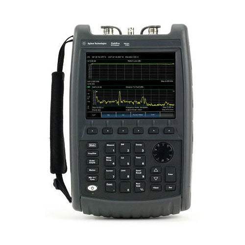
The Agilent FieldFox RF Analyzer N9912A is a handheld, multi-function RF analyzer built to test and maintain wireless networks in the field. Positioned as the world's most integrated handheld RF analyzer, it consolidates cable and antenna analysis, spectrum analysis, network analysis, power metering, and vector voltmeter measurement into a single portable instrument, so a technician can carry one tool to a cell site instead of several.
The instrument targets the deployment and maintenance of increasingly complex wireless networks, where operating frequencies have climbed toward 5.8 GHz and service providers must build and maintain more base stations in the same coverage area. Because fifty to sixty percent of cell site problems trace to faulty cables, connectors, and antennas, the FieldFox makes return loss, VSWR, insertion loss/transmission, one-port cable loss, and distance-to-fault measurements to keep feed-line and antenna systems healthy. Its built-in spectrum analysis is aimed at locating internal and external interference, a major source of cell site problems. Listed vector voltmeter applications include cable trimming of phase-matched cables, verifying the isolation of two-port components, and radio navigation work such as VHF omnidirectional radio range (VOR) and instrument landing systems (ILS).
ValueTronics stocks and holds its own inventory in a 20,000 sq ft secure warehouse at 1675 Cambridge Drive in Elgin, Illinois, serving test-and-measurement buyers since 1992. Every used unit is inspected and functionally verified in-house before it ships, while new units ship factory-sealed exactly as received from the manufacturer, so you can order with confidence in either condition.
This instrument carries Agilent Technologies branding. Hewlett-Packard spun out its test-and-measurement business as Agilent Technologies in 1999, and Agilent's electronic measurement business was subsequently established as Keysight Technologies in 2014.
| Specification | Value |
|---|---|
| Cable and Antenna Analyzer (Option 104 or 106) | |
| Frequency range (Option 104) | 2 MHz to 4 GHz |
| Frequency range (Option 106) | 2 MHz to 6 GHz |
| Frequency reference accuracy | ±2 ppm |
| Frequency reference aging rate | ±1 ppm/yr |
| Frequency reference temperature stability | ±1 ppm over -10 to 55 ºC |
| Frequency resolution (2 MHz to 1.6 GHz) | 2.5 kHz |
| Frequency resolution (> 1.6 GHz to 3.2 GHz) | 5 kHz |
| Frequency resolution (> 3.2 GHz to 6 GHz) | 10 kHz |
| Measurement speed, Return loss | 1.5 ms/point (nominal), 1.75 GHz to 3.85 GHz, 1001 points, Cal ON |
| Measurement speed, Distance to fault | 2.4 ms/point (nominal), 0 to 500 ft, 601 points, Cal ON |
| Data points | 101, 201, 401, 601, 801, 1001 |
| Directivity, Corrected | > 42 dB |
| Directivity, QuickCal (Option 111) | > 42 dB (typical) |
| Source match, Corrected | > 36 dB |
| Source match, QuickCal (Option 111) | ≥ 35 dB (typical) |
| Reflection tracking, Corrected | ± 0.06 dB |
| Reflection tracking, QuickCal (Option 111) | ± 0.15 dB (typical) |
| Dynamic Range | |
| Reflection (RF Out port), 2 MHz to 4 GHz | 60 dB (typical) |
| Reflection (RF Out port), > 4 GHz to 6 GHz | 55 dB (typical) |
| Transmission measurement (Option 110), 2 MHz to 2 GHz | 72 dB (typical) |
| Transmission measurement (Option 110), > 2 GHz to 3 GHz | 67 dB (typical) |
| Transmission measurement (Option 110), > 3 GHz to 5 GHz | 58 dB (typical) |
| Transmission measurement (Option 110), > 5 GHz to 6 GHz | 49 dB (typical) |
| Output power range, High power 2 MHz to 4 GHz | < +8 dBm, +6 dBm (nominal) |
| Output power range, High power > 4 GHz to 6 GHz | < +7 dBm, +2 dBm (nominal) |
| Output power range, Low power 2 MHz to 4 GHz | < -23 dBm, -25 dBm (nominal) |
| Output power range, Low power > 4 GHz to 6 GHz | < -24 dBm, -25 dBm (nominal) |
| Immunity to interference | +16 dBm (nominal) |
| Maximum input level (RF Out port) | +23 dBm |
| Maximum input DC voltage (RF Out port) | ±50 VDC |
| Cable and Antenna Measurements | |
| Return loss display range | 0 to 100 dB |
| Return loss resolution | 0.01 dB |
| VSWR display range | 0 to 100 |
| VSWR resolution | 0.01 |
| Distance to fault, number of points | 101, 201, 401, 601, 801, 1001 |
| Cable loss (1-port) | Terminated cable under test with short |
| Insertion loss (2-ports) | Requires Option 110 |
| Network Analysis (Option 303) | |
| S11 | Vector measurement, S11 magnitude and S11 phase |
| S21 | Scalar measurement, S21 magnitude (requires Option 110) |
| Display | Log, linear, phase, VSWR, Smith chart |
| Calibration types | Mechanical cal; QuickCal; Normalization; Automatic cal update with frequency change or number of points change |
| IF bandwidth selections | 300 Hz, 1 kHz, 3 kHz, 10 kHz and 30 kHz |
| Spectrum Analyzer (Option 230 or 231) | |
| Frequency range (Option 104 / 230) | 100 kHz to 4 GHz, usable to 5 kHz |
| Frequency range (Option 106 / 231) | 100 kHz to 6 GHz, usable to 5 kHz, tunable to 6.1 GHz |
| Frequency reference accuracy | ±2 ppm |
| Frequency aging | ± 1 ppm/yr |
| Frequency reference temperature stability | ± 1 ppm over -10 to 55 °C |
| Frequency span range | 0 Hz (zero span), 10 Hz to maximum frequency |
| Span accuracy | ±(2 x RBW centering + horizontal resolution) |
| Span resolution | 1 Hz |
| Resolution bandwidth (RBW), zero span | 300 Hz to 1 MHz in 1-3-10 sequence; 2 MHz |
| Resolution bandwidth (RBW), non-zero span | 10 Hz to 300 kHz in 1/1.5/2/3/5/7.5/10 sequence; 1 MHz, 2 MHz |
| RBW accuracy | 1 kHz to 1 MHz: ± 5% (nominal); 10 Hz to 100 kHz non-zero span: ± 1% (nominal); 2 MHz: ± 10% (nominal); 300 Hz zero span: ± 10% (nominal) |
| RBW selectivity (-60 dB / -3 dB) | 4:1 (nominal) |
| Video bandwidth (VBW) range | 1 Hz to 2 MHz in 1/1.5/2/3/5/7.5/10 sequence |
| Noise sidebands (CF = 1 GHz), 10 kHz offset | -88 dBc/Hz (typical) |
| Noise sidebands (CF = 1 GHz), 30 kHz offset | -89 dBc/Hz (typical) |
| Noise sidebands (CF = 1 GHz), 100 kHz offset | -95 dBc/Hz (typical) |
| Noise sidebands (CF = 1 GHz), 1 MHz offset | -115 dBc/Hz (typical) |
| Sweep acquisition range (span > 0 Hz) | 1 to 5000 data acquisitions per trace point |
| Trace points | 101, 201, 401, 601, 801, 1001 points, default is 401 |
| Measurement range | Displayed average noise level (DANL) to +20 dBm |
| Input attenuator range | 0 to 31 dB, 1 dB steps |
| Maximum DC voltage at RF In port | ±50 VDC |
| Maximum input power at RF In port | +27 dBm (0.5 W) |
| DANL, Preamplifier OFF, 10 MHz to 2.4 GHz | -130 dBm (typical) |
| DANL, Preamplifier OFF, > 2.4 GHz to 5.0 GHz | -125 dBm (typical) |
| DANL, Preamplifier OFF, > 5.0 GHz to 6.0 GHz | -119 dBm (typical) |
| DANL, Preamplifier ON (Option 235), 10 MHz to 2.4 GHz | -148 dBm (typical) |
| DANL, Preamplifier ON (Option 235), > 2.4 GHz to 5.0 GHz | -145 dBm (typical) |
| DANL, Preamplifier ON (Option 235), > 5.0 GHz to 6.0 GHz | -138 dBm (typical) |
| Total absolute amplitude accuracy, 2 MHz to 10 MHz | ±1.8 dB, ±0.60 dB (typical) |
| Total absolute amplitude accuracy, > 10 MHz to 3.0 GHz | ±1.5 dB, ±0.50 dB (typical) |
| Total absolute amplitude accuracy, > 3.0 GHz to 5.0 GHz | ±1.9 dB, ±0.60 dB (typical) |
| Total absolute amplitude accuracy, > 5.0 GHz to 6.0 GHz | ±2.1 dB, ±0.60 dB (typical) |
| Second harmonic distortion (SHI), 2 MHz to 1.35 GHz | < -70 dBc, +40 dBm SHI (nominal) |
| Second harmonic distortion (SHI), 1.35 GHz to 3.0 GHz | < -80 dBc, +50 dBm SHI (nominal) |
| Third order intermodulation distortion (TOI) | < -96 dBc, +18 dBm TOI (nominal) |
| Residual responses, 20 MHz to 3 GHz | -90 dBm (nominal) |
| Residual responses, > 3 GHz to 6 GHz | -85 dBm (nominal) |
Important: Maximum DC voltage at the RF In and RF Out ports: +/-50 VDC. Maximum input power at the RF In port: +27 dBm (0.5 W).
Important: The N9912A base unit is a one-port 4 GHz cable and antenna analyzer with broadband calibration, CalReady, and standard mechanical cal kit support; spectrum analyzer, transmission measurement, network analysis, power meter, and vector voltmeter functions each require their respective options (104/106, 110, 230/231, 235, 302, 303, 308).
Important: Power meter measurements (Option 302) require an Agilent U2000 Series USB power sensor, which is not included with the base unit and must be ordered separately; the sensor covers 9 kHz to 24 GHz (sensor dependent).
Important: Spectrum analyzer (Option 230/231) start frequency is 100 kHz, usable to 5 kHz.
Important: When an additional device (such as a jumper cable or attenuator) is added to the test port, the instrument must be calibrated using a calibration kit (cal kit).
Recommended pairing: with external USB power sensor support (Option 302), the FieldFox works with the Agilent U2000 Series USB power sensor for true average power measurements up to 24 GHz.
This pre-owned unit is inspected and functionally verified in-house before it ships and is backed by our pre-owned warranty. To confirm its exact condition, firmware revision, installed options, or included accessories for your application before ordering, contact our Test Architects.
ValueTronics supplies both new and used test and measurement equipment. New units ship factory-sealed, exactly as received from the manufacturer; every used unit is inspected and functionally verified in-house at our 20,000 sq ft secure facility in Elgin, Illinois before it ships. Our Test Architects can help you select the condition, calibration, and configuration that fit your application.
Please review the Manufacturer's Data Sheet to verify published specifications. Feedback on this webpage is always welcome — please reach out to your Test Architect at any time for questions or concerns. Thank you, we truly appreciate you being our customer.
Model No
Agilent
Condition
Pre-Owned
Manufacturer
Agilent
Cabant_ana_freq
6 GHz
["10
VNA time domain
30
Remote control capability
104
4 GHz RF vector network analyzer
transmission/reflection
110
Transmission measurement
111
QuickCal
210
VNA transmission/reflection
211
VNA full 2-port S-parameters
215
TDR CABLE MEASUREMENTS
230
Spectrum analyzer
231
6 GHz spectrum analyzer (requires Option 106)
233
Spectrum analyzer
235
Preampliier for spectrum analyzer (requires Option 230 or 231)
236
Interference analyzer and spectrogram
238
Spectrum analyzer time gating
302
External USB power sensor support
303
Network analysis capability
305
Cable and antenna analyzer
307
GPS receiver
308
Vector voltmeter
309
DC bias variable-voltage source
310
Built-in power meter
350
REAL-TIME SPECTRUM ANALYZER (RTSA)"]

30+ Years in Business
Secure Payments
Sell Test Equipments
Knowledgeable Staff
On-site Lab
30+ Years in Business
Secure Payments
Sell Test Equipments
Knowledgeable Staff
On-site Lab
Request A Quote
 Chat Live
 Contact Us
 sales@valuetronics.com