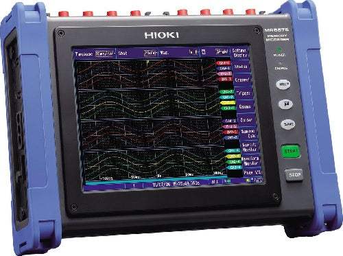
The Hioki MR8875 Memory HiCorder is a multi-channel high-speed data logger built into a compact, A4-size footprint for portability. It uses a plug-in module architecture: by selecting and installing up to four input modules, measurement capability ranges from 16 analog channels to 60 thermocouple temperature channels. The same instrument can mix and record voltage, temperature, strain, and CAN signals at 16-bit resolution, recording sensor signal waveforms faithfully using the same working principle as a digital oscilloscope writing to large-capacity internal memory.
Hioki documents the MR8875 across several measurement scenarios: verifying the operation of multi-axis industrial robots by mixing sensor outputs, strain, control signals, voltage, and temperature on multiple channels; R&D and science experiments, including recording and evaluating sensor output and use as a flatbed X-Y recorder; and development testing for construction machinery, agricultural machinery, and automobiles. Additional applications include battery evaluation — measuring individual cell voltage and EV battery testing — characteristics testing of power equipment such as load rejection and circuit breaker testing, and primary- and secondary-side measurement of inverter and motor systems.
ValueTronics stocks and holds its own test-and-measurement inventory in a 20,000 sq ft secure warehouse at 1675 Cambridge Drive in Elgin, Illinois. That combination lets engineers source the right logger and input-module configuration with confidence in what arrives on the bench.
The MR8875 is a single main unit whose capability is defined by the input modules installed in its four user-accessible slots. Rather than choosing between fixed instrument tiers, you select among Hioki's plug-in modules — the Analog Unit MR8901, Voltage/Temp Unit MR8902, Strain Unit MR8903, CAN Unit MR8904, and high-voltage Analog Unit MR8905 — and mix them in any combination to suit the measurement at hand.
Because modules are user-installable and can be changed after purchase, the same main unit moves between voltage, temperature, strain, and CAN measurement tasks. The comparison table below summarizes how the individual modules differ in channel count, measurement target, range, resolution, and sampling so the configuration can be matched to the signals being recorded.
Each new item shown below — the MR8875 main unit and its individual input modules — is offered on its own dedicated product page with condition-matched pricing, so you can build the exact configuration your application requires by adding the specific units you need.
The MR8875 main unit provides the recording engine, 8.4-inch SVGA touch-screen display, 32 Mega-word internal memory, SD and USB storage, 100BASE-TX LAN, and two standard pulse-input channels; it cannot operate alone and requires at least one input module to be installed.
The modules diverge primarily in measurement target and front-end specification. The MR8901 handles general voltage (100 mV to 200 V f.s., 4 µV resolution) at up to 500 kS/s; the MR8905 is the high-voltage unit (10 V to 1000 V f.s., direct 1000 V CAT II / 600 V CAT III) with switchable instantaneous and AC-RMS modes; the MR8902 adds thermocouple temperature measurement across 15 channels; the MR8903 targets strain and high-sensitivity voltage down to 1 mV f.s.; and the MR8904 provides CAN bus acquisition with two ports per unit.
Sampling and isolation also differ by module: the MR8901 and MR8905 sample all channels simultaneously at 500 kS/s (2 µs), the MR8903 at 200 kS/s (5 µs), and the MR8902 scans at a 10 msec rate suited to its slower temperature and DC-voltage measurements. Analog-unit channels are isolated from each other and from the main unit, while CAN ports, standard logic terminals, and standard pulse terminals share a common ground. Refer to the comparison table for each module's exact ranges, resolutions, and channel counts.
| Model | Channels | Measurement Type | Max Input / Range |
|---|---|---|---|
| MR8875 | Up to 60 (4 module slots) | Multi-channel logger mainframe | 1000 V direct input (with MR8905) |
| MR8901 | 4 | Voltage | 200 V f.s. (100 mV f.s. to 200 V f.s.) |
| MR8902 | 15 | Voltage / Temperature | 100 V f.s. (voltage) / 2000°C f.s. (temperature) |
| MR8903 | 4 | Voltage / Strain | 20 mV f.s. (voltage) / 20,000 µε f.s. (strain) |
Additional differences in specifications beyond the few shown above are not listed here — see each model's full specifications below.
| Specification | Value |
|---|---|
| General / Basic Specifications (accuracy guaranteed for 1 year) | |
| Measurement function | High-speed recording |
| Number of input modules that can be installed | Up to 4 slots, user installable in any combination by plugging into the main unit |
| Max. sampling rate | MR8901/MR8905: 500 kS/s (2 µs period, all channels simultaneous); MR8902: 10 msec (channel scanning); MR8903: 200 kS/s (5 µs period, all channels simultaneous); External sampling: 200 kS/s (5 µs period) |
| Storage memory capacity | Total 32 Mega-words (memory expansion: none, 8 Mega-words/module); 1 word = 2 bytes, therefore 32 Mega-words = 64 Mega-bytes |
| External storage | SD card slot × 1, USB memory stick (USB 2.0 standard); FAT-16 or FAT-32 format on SD or USB |
| Backup functions (at 23°C/73°F) | Clock and parameter setting backup: at least 10 years; Waveform backup function: none |
| Interfaces | LAN × 1: 100BASE-TX (DHCP, DNS supported, FTP server/client, web server, send E-mail, command control); USB series mini-B receptacle × 1; USB series mini-A receptacle × 2 (USB memory stick, USB mouse, USB keyboard) |
| External control connectors | External trigger input, trigger output, external sampling input, pulse input × 2, external input × 3, external output × 2 |
| External power supply | Three lines, +5 V, 2 A total output, common GND with the body GND (Differential probe 9322 can not be used) |
| Operating temperature and humidity (no condensation) | -10°C to 40°C (14°F to 104°F), 80% rh or less; 40°C to 45°C, 60% rh or less; 45°C to 50°C, 50% rh or less. Battery pack operation: 0°C to 40°C, 80% rh or less. Battery charging: 10°C to 40°C, 80% rh or less. Storage: -20°C to 40°C, 80% rh or less |
| Applicable standards | Safety: EN61010-1; EMC: EN61326, EN61000-3-2, EN61000-3-3 |
| Compliant standards | Anti-vibration: JIS D1601: 1995 5.3 (1) (corresponds to Class 1: passenger car, condition: class A) |
| Power supply | AC adapter Z1002: 100 to 240 V AC (50/60 Hz); Battery Pack Z1003: 7.2 V DC; Continuous operation time: one hour with back light on; DC power supply: 10 to 28 V DC |
| Charging function (at 23°C/73°F) | Recharging time: approx. 3 hours (using the AC adapter and main unit to recharge the Battery Pack Z1003) |
| Power consumption | 56 VA (AC adapter Z1002 or external DC power supply); 36 VA (battery pack) |
| Dimensions and weight | Approx. 298W × 224H × 84D mm (11.73W × 8.82H × 3.31D in.), 2.4 kg (84.7 oz.), excluding input modules and battery pack |
| Supplied accessories | Instruction Manual × 1, Measurement Guide × 1, AC Adapter Z1002 × 1, Protection Sheet × 1, USB Cable × 1, Shoulder Strap × 1, Application Disk (Wave viewer Wv, communication commands table, CAN Editor) × 1 |
| Measurement Function (High-speed recording) | |
| Time axis | 200 µs/div, 500 µs/div, 1 ms/div to 500 ms/div, 1 s/div to 5 min/div; 21 ranges, external sampling (max. 200 kS/s) |
| Recording intervals with real-time save on | 2 µs/S (up to 2 channels), 5 µs/S (up to 8 channels), 10 µs/S (up to 16 channels), 20 µs/S (up to 30 channels), 50 µs/S (up to 64 channels), 100 µs/S (no limit on number of channels in use) |
| Accuracy of time axis | ±0.0005% |
| Time axis resolution | 100 points/div |
| Recording length (with MR8901 × 4, logic and pulse inputs off) | 25 to 20,000 div, 50,000 div, or user-configurable from 5 to 80,000 div in 1 div increments |
| Waveform expansion/compression | Time axis: × 10 to × 2 or × 1, × 1/2 to × 1/50,000; Voltage axis: × 100 to × 2 or × 1, × 1/2 to × 1/10 |
| Pre-trigger | Pre-trigger data can be recorded for an interval set in steps ranging from 0% to 100% of the recording length |
| Post-trigger | Post-trigger data can be recorded for an interval set in steps ranging from 0% to 40% of the recording length |
| Real-time data save | On/off selectable; waveforms saved as binary data to the SD memory card at each interval (cannot save in real-time to USB memory; use only Hioki SD memory cards); endless loop or normal saving |
| Auto data save | Select from off, waveform data (binary or CSV), numerical calculation results, image data (compressed BMP or PNG) to SD or USB memory |
| Data protection | In the event of a power outage during saving to storage media, the file is closed and then power is shut down (enabled 15 minutes after power on) |
| Memory segmentation | N/A |
| Display | |
| Display type | 8.4 inch SVGA-TFT color LCD (800 × 600 dots, touch screen); time axis 25 div × voltage axis 20 div, X-Y waveform 20 div × 20 div |
| Screen settings | Waveform split screen (1, 2, or 4), X-Y 1 & X-Y 2 screens, time axis + X-Y waveform screen, sheet display (sheet ALL, sheet 1 to 4 selectable) |
| Real-time value monitor | Values for all channels can be monitored during measurement (instantaneous value, average value, P-P value, max. value, min. value) |
| Trigger Functions | |
| Mode | Single, repeat |
| Timing | Start, stop, and start & stop (separate trigger conditions can be set to start and stop) |
| Trigger level resolution | Analog: 0.1% f.s. (f.s. = 20 div); Pulse integration: 0.002% f.s.; Pulse rotation count: 0.02% f.s. |
| Trigger filter | Set by number of samples (10 to 1000 points, or off) |
| Trigger output | Open drain output (with 5 V output, active low); Output voltage: 4.0 to 5.0 V (high), 0 to 0.5 V (low); Output pulse width: level or pulse (Pulse: 2 ms ±10%) |
| Pulse Input Section | |
| No. of channels | 2 channels, push-button type terminal, not isolated (common GND with main unit) |
| Mode | Rotation, integration |
| Input form | No-voltage 'a' contact, no-voltage 'b' contact, open collector or voltage input; Input resistance: 1.1 MΩ |
| Max. allowable input | 0 V to 50 V DC |
| Detection level | 4 V: (high: over 4.0 V, low: 0 to 1.5 V); 1 V: (high: over 1.0 V, low: 0 to 0.5 V) |
| Pulse input period | With filter off: 200 µs or more; With filter on: 100 ms or more |
| Other Functions | |
| External sampling | Maximum input: up to 10 V DC; Maximum input frequency: 200 kHz |
| Numerical calculation | Up to 8 calculations simultaneously (average, rms, peak to peak, max, min, period, frequency, rise/fall time, area, etc.) |
| FFT calculations (Ver. 2.01 or later) | Up to 4 simultaneously; Number of points: 1,000 to 10,000; Frequency range: 1.33 mHz to 400 kHz; Calculation precision: 32-bit floating point, IEEE single-precision |
Important: Real-time data saving and operation are guaranteed only with genuine Hioki SD memory cards.
Important: The MR8875 main unit (Model No. MR8875, Max. 16 to 60ch, 32 MWord memory, main unit only) cannot operate alone; input modules must be installed separately.
Important: The Analog Unit MR8905 does not include input cables. Separate purchase of the optional Connection Cable Set L4940 (× 2) and Alligator Clip Set L4935 (× 2), which consists of clips that fit onto the ends of the cables, is required.
Important: Use only HIOKI SD memory cards and USB memory sticks; compatibility and performance are not guaranteed for cards made by other manufacturers.
Important: A separate power supply (CT955x / Sensor Unit CT9555) is required in order to use a high-precision current sensor with the MR8875.
Important: When using the external power supply (three lines, +5 V output), the Differential probe 9322 can not be used.
Important: The recordable measurement data to a 2 GB SD memory card is approximately 90% of the time shown; the upper limit is 1,000 days but operation is guaranteed for 1 year.
Usage tip: pair the standard Analog Unit MR8901 with the Differential Probe P9000 series to enable high-voltage 1,000 V (CAT III) measurement; the P9000-02 adds RMS-level measurement of AC power lines.
This is a brand-new, factory-sealed unit, supplied exactly as it arrives from the manufacturer and backed by the full manufacturer warranty. For the exact configuration, available options, included accessories, or current lead time for your application, our Test Architects can confirm the details before you order.
ValueTronics supplies both new and used test and measurement equipment. New units ship factory-sealed, exactly as received from the manufacturer; every used unit is inspected and functionally verified in-house at our 20,000 sq ft secure facility in Elgin, Illinois before it ships. Our Test Architects can help you select the condition, calibration, and configuration that fit your application.
Please review the Manufacturer's Data Sheet to verify published specifications. Feedback on this webpage is always welcome — please reach out to your Test Architect at any time for questions or concerns. Thank you, we truly appreciate you being our customer.
Model No
Hioki
Condition
Factory New
Manufacturer
Hioki

30+ Years in Business
Secure Payments
Sell Test Equipments
Knowledgeable Staff
On-site Lab
30+ Years in Business
Secure Payments
Sell Test Equipments
Knowledgeable Staff
On-site Lab
Request A Quote
 Chat Live
 Contact Us
 sales@valuetronics.com