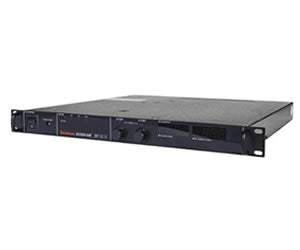
The Elgar DCS Family comprises 1 kW, 1.2 kW, and 3 kW DC programmable switching power supplies that use switch-mode technology to achieve high power density in a low-profile chassis. Through its packaging approach, the series delivers continuous full output power—1 kW, 1.2 kW, or 3 kW—in any voltage and current combination within each model's rated output limits. Voltage and current settings are adjusted with 10-turn potentiometers and displayed simultaneously, while front-panel LEDs indicate overtemperature, remote programming, shutdown, overvoltage protection, status, and constant-voltage/constant-current mode operation.
A programmable DC power supply provides regulated, adjustable direct-current voltage and current for powering and testing electronic devices and subsystems on the bench or within automated systems. The DCS series supports selectable remote programming of voltage, current, and overvoltage protection, and offers a remote start/stop and interlock input that is TTL compatible or driven by an AC voltage signal or a contact closure, allowing the supply to be integrated into a larger controlled test setup.
ValueTronics stocks and holds its own inventory in a 20,000-square-foot secure warehouse at 1675 Cambridge Drive in Elgin, Illinois. Every used unit we sell is inspected and functionally verified in-house before it ships, while new units leave the building factory-sealed exactly as received, so buyers receive equipment handled to a consistent standard whichever condition they choose.
Elgar Electronics Corporation was a San Diego-based manufacturer of programmable power sources that became part of AMETEK Programmable Power following AMETEK's acquisition of the business.
The DCS Family is organized into three power tiers—1 kW, 1.2 kW, and 3 kW—each offered in a range of fixed voltage/current models identified by an output suffix, from the 0-8 VDC models through the 0-600 VDC models. Every model delivers its full rated power continuously in any volt/amp combination within its rated voltage and current limits.
All three tiers share the same core architecture: switch-mode conversion, 10-turn voltage and current potentiometers with simultaneous display, 0.1% line and load regulation, crowbar overvoltage protection, and the same internal-interface option set. The tiers differ primarily in total output power, chassis size, and input-power configuration.
Each model in the family below is its own dedicated product page with condition-matched pricing for pre-owned units. Compare the voltage and current ratings across the models to match the supply to your output requirement, then select the listing for the specific model and condition you need.
The clearest difference between the tiers is output power and packaging. The 1 kW and 1.2 kW models share a 1U, 1.75-inch-high, 19-pound chassis and run from single-phase AC (100-132 VAC or 200-250 VAC), whereas the 3 kW model uses a 2U, 3.5-inch-high, 33-pound chassis and accepts three-phase 190-250 VAC or single-phase 200-250 VAC, limited to 2.5 kW on single phase.
Within each tier, the individual models set the voltage and current envelope, spanning 0-8 VDC to 0-600 VDC and 1.7 A to 350 A across the family; consult the comparison table for each model's exact ratings, ripple, and efficiency. The 3 kW models also add push-button control of standby, OVP reset, and remote/local selection, and regulatory coverage differs in that UL1012 and CSA 22.2 #220 apply to the 1 kW and 1.2 kW models. Match every capability to the specific model's row in the table before ordering.
| Model | Output Voltage | Output Current | Output Power |
|---|---|---|---|
| DCS 80-13E | 0-80 VDC | 0-13 A | 1 kW |
| DCS 8-125E | 0-8 VDC | 0-125 A | 1 kW |
| DCS 10-100E | 0-10 VDC | 0-100 A | 1 kW |
| DCS 20-50E | 0-20 VDC | 0-50 A | 1 kW |
Additional differences in specifications beyond the few shown above are not listed here — see each model's full specifications below.
| Specification | Value |
|---|---|
| Output (Common) | |
| Voltage Resolution | 0.02% |
| Typical Resolution (CV/CC mode) | 0.02% |
| Regulation (Line or Load), Voltage | 0.1% |
| Regulation (Line or Load), Current | 0.1% |
| Combined Regulation (Line and Load) | 0.2% |
| Transient Response | Typically recovers in <1 ms to 1% of steady-state output voltage (within 1% of Vmax) for 70-100% or 100-70% load change. 500 µs typical |
| Stability | ±0.05% of maximum voltage or current over 8 hours after 30 minute warm-up time at fixed line, load and temperature |
| Temperature Coefficient, Voltage | 0.02%/°C of maximum output voltage |
| Temperature Coefficient, Current | 0.03%/°C of maximum output current |
| Voltage Drift (Typ.) | 0.05% Vmax |
| Current Drift (Typ.) | 0.05% Io Max. |
| Input | |
| 1 kW Input Voltage/Frequency | 200-250 VAC, single phase, 8A typical, 47-63 Hz; or 100-132 VAC, single phase, 15A typical, 47-63 Hz, internal jumper selectable (See M1 option) |
| 1.2 kW Input Voltage/Frequency | 200-250 VAC, single phase, 9A typical, 47-63 Hz; or 100-132 VAC, single phase, 18A typical, 47-63 Hz, internal jumper selectable (See M1 option) |
| 3 kW Input Voltage/Frequency | 190-250 VAC, three phase, 14A typical, 47-63 Hz; or 200-250 VAC, single phase, 20A typical, 47-63 Hz |
| 3 kW Single-Phase Power Limit | Maximum power output of 3 kW supplies must be limited to 2.5 kW for single phase input |
| Soft Start | Line current is lower than full load peak value during turn-on or power application after restart |
| Common | |
| Operating Temperature | 0°C to 50°C (no derating), 50°C to 70°C (derate 2%/°C above 50°C) |
| Storage Temperature | -55°C to 85°C |
| Humidity Range | 0 to 80% RH, non condensing |
| Meter Accuracy | 1% of full scale + 1 count |
| Max. Voltage Differential from Output to Safety Ground | 150 VDC |
| Remote Start/Stop and Interlock | TTL compatible input or 12-250 VAC (12-130 VDC) or a contact closure |
| Cooling | Internal fan, overtemperature shutdown if internal heat sink exceeds set temperature |
| Remote Sense | The maximum allowed sense line drop is 4V per line (2V on the DCS 8 and 10V 1kW and 1.2 kW models and 1V/line for all 3 kW models) |
| Remote Programming | External jumper via rear panel connector J3 |
| Overvoltage Protection | Crowbar type adjustable from 5-110% of rated output using front panel control (local or remote program selectable via J3 jumper) |
| Remote Analog Programming | |
| Linearity | ±1% |
| Accuracy | ±5% |
| Software | |
| LabVIEW Driver | LabVIEW driver for M9C/M85 programs can be downloaded at no cost at www.elgar.com |
| Regulatory Compliance | |
| Compliance | CE Mark (1-3 kW); FCC Part 15 Class A, UL1012, CSA 22.2 #220 (1 and 1.2 kW only) |
| Warranty | 5 Year Warranty |
| Dimensions | |
| 1 kW and 1.2 kW | 1U or 1.75" (44 mm) H x 19" (482 mm) W x 17.5" (444 mm) D |
| 3 kW | 2U or 3.5" (88 mm) H x 19" (482 mm) W x 17.5" (444 mm) D |
| Weight | |
| 1 kW and 1.2 kW (Net) | 19 lbs. (8.6 kg) |
| 3 kW (Net) | 33 lbs. (15 kg) |
| 1 kW and 1.2 kW (Shipping) | 24 lbs. (10.9 kg) |
| 3 kW (Shipping) | 42 lbs. (19 kg) |
| Output Ratings — DCS 1 kW Models (Voltage / Current @ 50 °C / Ripple RMS / Noise P-P / Transient Response Typ. / Efficiency Typ. / Case) | |
| DCS 8-125E | 0-8 VDC / 0-125 A / 4 mV / 60 mV / 500 µs / 82% / Case I |
| DCS 10-100E | 0-10 VDC / 0-100 A / 4 mV / 60 mV / 500 µs / 82% / Case I |
| DCS 20-50E | 0-20 VDC / 0-50 A / 4 mV / 60 mV / 500 µs / 82% / Case I |
| DCS 33-33E | 0-33 VDC / 0-33 A / 4 mV / 60 mV / 500 µs / 84% / Case I |
| DCS 40-25E | 0-40 VDC / 0-25 A / 4 mV / 60 mV / 500 µs / 84% / Case I |
| DCS 50-20E | 0-50 VDC / 0-20 A / 4 mV / 60 mV / 500 µs / 84% / Case I |
| DCS 60-18E | 0-60 VDC / 0-18 A / 4 mV / 60 mV / 500 µs / 86% / Case I |
| DCS 80-13E | 0-80 VDC / 0-13 A / 4 mV / 60 mV / 500 µs / 86% / Case I |
| DCS 100-10E | 0-100 VDC / 0-10 A / 6 mV / 60 mV / 500 µs / 86% / Case I |
| DCS 150-7E | 0-150 VDC / 0-7 A / 12 mV / 160 mV / 500 µs / 86% / Case I |
| DCS 300-3.5E | 0-300 VDC / 0-3.5 A / 20 mV / 200 mV / 500 µs / 86% / Case I |
| DCS 600-1.7E | 0-600 VDC / 0-1.7 A / 50 mV / 300 mV / 500 µs / 86% / Case I |
| Output Ratings — DCS 1.2 kW Models (Voltage / Current @ 50 °C / Ripple RMS / Noise P-P / Transient Response Typ. / Efficiency Typ. / Case) | |
| DCS 8-140E | 0-8 VDC / 0-140 A / 5 mV / 60 mV / 500 µs / 82% / Case I |
| DCS 10-120E | 0-10 VDC / 0-120 A / 5 mV / 60 mV / 500 µs / 82% / Case I |
| DCS 20-60E | 0-20 VDC / 0-60 A / 5 mV / 60 mV / 500 µs / 82% / Case I |
| DCS 33-36E | 0-33 VDC / 0-36 A / 5 mV / 60 mV / 500 µs / 84% / Case I |
| DCS 40-30E | 0-40 VDC / 0-30 A / 5 mV / 60 mV / 500 µs / 84% / Case I |
| DCS 50-24E | 0-50 VDC / 0-24 A / 5 mV / 60 mV / 500 µs / 84% / Case I |
| DCS 60-20E | 0-60 VDC / 0-20 A / 5 mV / 60 mV / 500 µs / 85% / Case I |
| DCS 80-15E | 0-80 VDC / 0-15 A / 5 mV / 60 mV / 500 µs / 85% / Case I |
| DCS 100-12E | 0-100 VDC / 0-12 A / 10 mV / 60 mV / 500 µs / 85% / Case I |
| DCS 150-8E | 0-150 VDC / 0-8 A / 15 mV / 160 mV / 500 µs / 85% / Case I |
| DCS 300-4E | 0-300 VDC / 0-4 A / 25 mV / 200 mV / 500 µs / 85% / Case I |
| Output Ratings — DCS 3 kW Models (Voltage / Current @ 50 °C / Ripple RMS / Noise P-P / Transient Response Typ. / Efficiency Typ. / Case) | |
| DCS 8-350E | 0-8 VDC / 0-350 A / 15 mV / 100 mV / 1000 µs / 82% / Case II |
Important: Maximum power output of the 3 kW models must be limited to 2.5 kW when operated from a single-phase input.
Important: Maximum voltage differential from output to safety ground is 150 VDC.
Important: Option M9C (Internal IEEE-488/RS 232 Interface) may not be combined with Option M51A or Option M85.
Important: Option M85 requires one master unit with the M9C option to control multiple units via a single GPIB address over a standard RS485 connector (3 ft. connector included).
This pre-owned unit is inspected and functionally verified in-house before it ships and is backed by our pre-owned warranty. To confirm its exact condition, firmware revision, installed options, or included accessories for your application before ordering, contact our Test Architects.
ValueTronics supplies both new and used test and measurement equipment. New units ship factory-sealed, exactly as received from the manufacturer; every used unit is inspected and functionally verified in-house at our 20,000 sq ft secure facility in Elgin, Illinois before it ships. Our Test Architects can help you select the condition, calibration, and configuration that fit your application.
Please review the Manufacturer's Data Sheet to verify published specifications. Feedback on this webpage is always welcome — please reach out to your Test Architect at any time for questions or concerns. Thank you, we truly appreciate you being our customer.
Model No
Elgar
Condition
Pre-Owned
Manufacturer
Elgar
Dcsup_amps
0-13 A
Dcsup_volts
0-80 VDC
Dcsup_watts
1 kW
M1
Factory configured for 115 VAC input (1 kW units only)
M15
Fully isolated programming interface
M9A
IEEE-488 /RS-232C
M9C
Internal IEEE-488/RS 232 Interface (May not be combined with M51A or M85)

30+ Years in Business
Secure Payments
Sell Test Equipments
Knowledgeable Staff
On-site Lab
30+ Years in Business
Secure Payments
Sell Test Equipments
Knowledgeable Staff
On-site Lab
Request A Quote
 Chat Live
 Contact Us
 sales@valuetronics.com