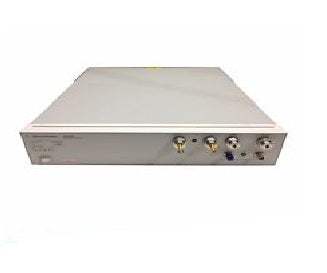

The Agilent N1015A modulation test set enables the expanded modulation bandwidths to 20 and 80 MHz at 2.5 and 10 Gb/s respectively. It also enables the 0.002 UI rms intrinsic jitter noise floor. Although the system is frequency agile, the 20 MHz expanded modulation range is limited to between 2.4 and 3.2 Gb/s. The 80 MHz expanded modulation range is limited to between 9.8 and 12.5 Gb/s.
Because the system is completely frequency agile, these tests can also be performed at any rate from below 50 Mb/s to above 12.5 Gb/s, such as the Fibre Channel 1063 Mb/s rate. Some utility for the STM-1/OC-3 (155 Mb/s) rate may be obtained. For 622 Mb/s (STM-4/OC-12) or 155 Mb/s (STM-1/OC-3), the Agilent N1015A modulation test set is not necessary for SDH/SONET standards tests.
The Agilent N1015A modulation test set allows STM-16/OC-48 (2488 Mb/s) and STM-64/OC-192 (9953Mb/s) compliant jitter measurements by providing an 80MHz modulation bandwidth and 0.002 UI rms intrinsic jitter noise floor. The signal is routed to the Agilent 86130A or 71612C pattern generator, thus producing data with the desired jitter. This data signal is then fed to the DUT. The recovered clock signal is routed to Channel 1 of the Agilent 71501D. The clock signal from the pattern generator is used as a reference signal and is routed to Channel 2 of the 71501D. Jitter transfer measurement accuracy is enhanced if signal harmonic content is suppressed. Thus low pass or band-pass filters are typically used in the measurement paths. The results of the jitter transfer measurement can be displayed in one of three ways: "Transfer Plot", "Delta Plot" and "Numerical Listing".
Model No
N1015A
Condition
Used
Manufacturer
Agilent
305
20 MHz Modulator