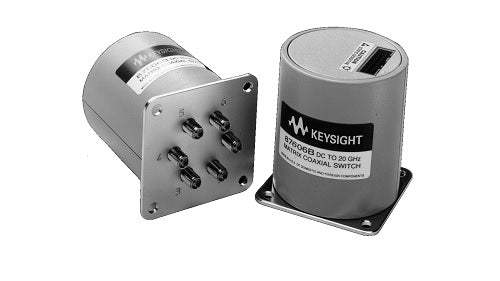
The Agilent 87606B is a six-port coaxial matrix switch covering DC to 20 GHz, designed for RF and microwave automated test systems. The datasheet describes it as a high-performance matrix switch offering improvements in insertion loss repeatability and isolation that support higher test system accuracy. The switch can be configured as a 3 x 3 or 2 x 4 blocking matrix, or as a 1 x 5 (SP5T) signal routing element, and uses magnetic latching with a self-interrupting drive circuit to reduce solenoid power consumption after switching is complete.
Per the datasheet, the 87606B is intended for automated test and measurement, signal monitoring, and signal routing applications. The longevity of the switch is positioned as a means to increase system uptime and reduce calibration cycles and switch maintenance in production test systems, satellite and antenna monitoring systems, and test instrumentation. The matrix architecture allows two of the six ports to be connected at a time, with all unselected RF ports terminated into internal 50 ohm loads.
Hewlett-Packard's test and measurement business was spun out as Agilent Technologies in 1999. In 2014, Agilent's electronic measurement business was transferred to Keysight Technologies, while Agilent retained its life sciences and chemical analysis lines. Components and instruments bearing the Agilent brand, including the 87606B, originate from this lineage.
The 87606B is a six-port coaxial matrix switch covering DC to 20 GHz, configurable per the datasheet as a 3 x 3 or 2 x 4 blocking matrix or as a 1 x 5 signal routing element. It is offered in two interface variants described in the ordering information: the standard model with a 16-pin ribbon cable connector and Option 100 with solder terminals in place of the ribbon connector.
Both variants share the same RF performance envelope, the same magnetic-latching mechanism, the same six SMA (f) ports, and the same drive voltage and current characteristics. The differences between the two are limited to the control interface and the availability of the open-all-ports function.
Each pre-owned 87606B configuration linked below is its own product page with condition-matched pricing. The model variant and option selection should match the control wiring already present in the system; the standard ribbon cable and the Option 100 solder-terminal variants are not interchangeable without rewiring the drive interface.
The standard 87606B and the 87606B Option 100 share identical RF specifications across the DC to 20 GHz range, but Option 100 substitutes solder terminals for the 16-pin ribbon cable connector and, per the datasheet, does not incorporate the open-all-ports feature available on the standard configuration. Selection between the two is driven by the control wiring approach in the target system.
The compare table below summarizes the two control-interface variants of the 87606B. RF frequency range, insertion loss, isolation, SWR, switching speed, life rating, and connector type are identical between the variants and reflect the published 87606B specifications.
The variant decision is a control-interface decision: the standard ribbon-cable model preserves the open-all-ports function on pin 16, while Option 100 provides a solder-terminal interface for hard-wired drive connections and omits the open-all-ports feature per the datasheet.
| Model | Frequency Range | Configuration | Isolation |
|---|---|---|---|
| 87606B | DC to 20 GHz | 3x3, 2x4, or 1x5 blocking matrix | 100 dB min to 12 GHz; 80 dB min 12-15 GHz; 70 dB min 15-20 GHz |
Additional differences in specifications beyond the few shown above are not listed here — see each model's full specifications below.
| Specification | Value |
|---|---|
| RF Performance | |
| Frequency range | DC to 20 GHz |
| Insertion loss | 0.34 dB + 0.033 x frequency (GHz) maximum |
| Isolation | 100 dB minimum to 12 GHz; 80 dB minimum from 12 to 15 GHz; 70 dB minimum from 15 to 20 GHz |
| SWR | 1.21 max DC to 4 GHz; 1.35 max 4 to 10 GHz; 1.5 max 10 to 15 GHz; 1.7 max 15 to 18 GHz; 1.9 max 18 to 20 GHz |
| Maximum power rating (switching) | 1 W average into 50 ohm internal loads |
| Maximum power rating (non-switching) | 50 W peak (10 μs max, not to exceed 1 W average) |
| Life | 5,000,000 cycles minimum (10 million typical) |
| Switching speed | 15 ms maximum |
| Supplemental Characteristics | |
| Insertion loss repeatability (measured at 25 °C) | 0.03 dB |
| Characteristic impedance | 50 ohms |
| RF connectors | SMA (f) |
| Switch Drive | |
| Supply voltage, Vcc | 20 V min, 24 V nom, 32 V max |
| Switching current (Vcc=24 VDC) | 200 mA nominal (per RF port closed or open) |
| Standby current (quiescent) | 25 mA min, 50 mA max |
| Environmental | |
| Operating temperature | -25 to 75 °C |
| Storage temperature | -55 to 85 °C |
| Temperature cycling | -55 to 85 °C, 10 cycles per MIL-STD-202F, Method 107D, Condition A (modified) |
| Vibration (operating) | 7 g: 5 to 2000 Hz at 0.25 in p-p |
| Vibration (survival) | 20 g: 20 to 2000 Hz at 0.06 in p-p, 4 min/cycle, 4 cycles/axis |
| Vibration (random) | 2.41 g (rms) 10 min/axis |
| Shock (half-sine) | 500 g at 0.5 ms, 3 drops/direction, 8 total |
| Shock (operating) | 50 g at 6 ms, 6 directions |
| Moisture resistance | 65 °C, 95% RH, 10 days per MIL-STD-202F, Method 106E |
| Altitude storage | 50,000 feet (15,240 meters) per MIL-STD-202F, Method 105C, Condition B |
| RFI | Per MIL-STD-461C, RE02, Part 4 |
| Magnetic field | <5 gauss 1/4 inch from surface |
| Physical | |
| Weight | 229 g (0.50 lb) |
| Body | 2-1/4 in. square flange, 2-1/2 in. long x 2-1/4 in. diameter body |
Please review the Manufacturer's Data Sheet to verify published specifications. Feedback on this webpage is always welcome — please reach out to your Test Architect at any time for questions or concerns. Thank you, we truly appreciate you being our customer.
Model No
Agilent
Condition
Used
Manufacturer
Agilent

30+ Years in Business
Secure Payments
Sell Test Equipments
Knowledgeable Staff
On-site Lab
30+ Years in Business
Secure Payments
Sell Test Equipments
Knowledgeable Staff
On-site Lab
Request A Quote
 Chat Live
 Contact Us
 sales@valuetronics.com