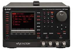
The WF1947/WF1948 is a multifunction generator that produces sine, square, pulse, ramp, noise, DC, and arbitrary waveforms from a single instrument. Sine output spans 0.01 µHz to 30 MHz, with square and pulse waveforms to 20 MHz and arbitrary waveforms to 10 MHz. Output is delivered through a 50 Ω unbalanced impedance at levels up to 20 Vp-p into an open circuit or 10 Vp-p into 50 Ω, with results shown on a 3.5-inch TFT color LCD.
A multifunction generator supplies the controlled stimulus signals an engineer uses to exercise a circuit or device under test — a known, repeatable input against which a measured output becomes meaningful. Beyond fixed waveforms, this instrument adds modulation, sweep, and burst capability, so the same unit can produce a steady tone, a swept frequency, a gated burst, or a modulated carrier as the test requires.
ValueTronics stocks and holds its own inventory in a 20,000-square-foot secure warehouse at 1675 Cambridge Drive in Elgin, Illinois.
The WF1947 and WF1948 form a single multifunction generator family that shares the same core signal engine: identical frequency ranges, output levels, modulation modes, sweep, and burst behavior across both models. Both produce sine output to 30 MHz, square and pulse to 20 MHz, and 16-bit arbitrary waveforms at 120 MS/s.
The two models are distinguished by channel configuration. The WF1947 is the single-channel member of the family, while the WF1948 adds two-channel ganged operation. Selecting between them comes down to whether the application requires one output or two coordinated outputs.
Each new model below is its own dedicated product page with condition-matched pricing. Compare the WF1947 and WF1948 in the table that follows and select the channel configuration that fits your application.
The primary difference between the two models is the number of output channels. The WF1947 provides a single channel; the WF1948 provides two channels with ganged operation, supporting independent two-channel use, two-phase (same-frequency) output, constant frequency difference, constant frequency ratio (N:M), and differential output (same frequency, amplitude, and DC offset with reversed waveform).
Power consumption tracks the channel count: the WF1947 draws up to 50 VA and the WF1948 up to 75 VA. The comparison table below lists these distinctions side by side.
| Model | Sine Frequency | Channels | Arbitrary Sample Rate |
|---|---|---|---|
| WF1947 | 30 MHz | 1 | 120 MS/s |
| WF1948 | 30 MHz | 2 | 120 MS/s |
Additional differences in specifications beyond the few shown above are not listed here — see each model's full specifications below.
| Specification | Value |
|---|---|
| Frequency Setting Ranges | |
| Sine | 0.01 μHz to 30 MHz |
| Square | 0.01 μHz to 20 MHz |
| Pulse | 0.01 μHz to 20 MHz |
| Ramp | 0.01 μHz to 5 MHz |
| Noise | The equivalent bandwidth is fixed to 26 MHz |
| DC | Frequency setting invalid |
| Arbitrary | 0.01 μHz to 5 MHz |
| Oscillation mode | Continuous, modulation, and sweep (continuous, single), gated and burst |
| Frequency and Phase | |
| Frequency setting resolution | 0.01 μHz |
| Frequency accuracy | ± (3 ppm of setting + 2 pHz), aging rate: ±1 ppm/year |
| Phase setting range | -1800.000° to +1800.000° |
| Output Characteristics – Amplitude | |
| Setting range | 0 Vp-p to 20 Vp-p/open, 0 Vp-p to 10 Vp-p/50 Ω, AC + DC ≤ ± 10 V/open |
| Setting resolution | 999.9 mVp-p or less: 4-digit/0.1 mVp-p; 1 Vp-p or greater: 5-digit/1 mVp-p |
| Accuracy | ± (0.8% of amplitude setting [Vp-p] + 2 mVp-p)/open (1 kHz sine wave, amplitude setting: 20 mVp-p/open or greater) |
| Setting unit | Vp-p, Vpk, Vrms, dBV, and dBm |
| Resolution of waveform | 16 bit (8 mVp-p/open or greater) |
| Output Characteristics – DC Offset | |
| Setting range | ±10 V/open, ±5 V/50 Ω |
| Setting resolution | ±499.9 mV or less: 4-digit/0.1 mV; ±0.5 V or greater: 5-digit/1 mV |
| Accuracy | ± (| 0.8% of DC offset setting [V] | + 5 mV + 0.5% of amplitude setting [Vp-p])/open (when outputting sine waves of 10 MHz or less) |
| Output Characteristics – General | |
| Output impedance | 50 Ω unbalanced |
| Output voltage of Synchronous/sub output | Sync signals TTL level, internal modulation signal -3 V to +3 V/open, sweep X drive 0 V to +3 V/open |
| Signal Characteristics – Sine Wave | |
| Amplitude frequency characteristics | Up to 100 kHz: ±0.1 dB; 100 kHz to 5 MHz: ±0.15 dB; 5 MHz to 20 MHz: ±0.3 dB; 20 MHz to 30 MHz: ±0.5 dB (±0.8 dB at 2.8 Vp-p/50 Ω or higher) (50 mVp-p to 10 Vp-p/50 Ω, reference frequency 1 kHz) |
| Total harmonic distortion | 20 Hz to 20 kHz: 0.04% or less (0.25 Vp-p to 10 Vp-p/50 Ω) |
| Harmonic spurious | Up to 1 MHz: -65 dBc or less, -70 dBc or less (typ.); 1 MHz to 3 MHz: -65 dBc or less; 3 MHz to 30 MHz: -65 dBc+6 dB/oct or less |
| Non-harmonic spurious | 0.5 Vp-p to 2 Vp-p/50 Ω: Up to 1 MHz -60 dBc or less, 1 MHz to 10 MHz -50 dBc or less, 10 MHz to 30 MHz -40 dBc or less; 2 Vp-p to 10 Vp-p/50 Ω: Up to 1 MHz -55 dBc or less, 1 MHz to 10 MHz -43 dBc or less, 10 MHz to 30 MHz -30 dBc or less (0.5 Vp-p to 10 Vp-p/50 Ω) |
| Signal Characteristics – Square Wave | |
| Duty variable | Variable range: Normal or extended (selectable); Normal range 0.0100% to 99.9900% (Upper limit (%): 100 - frequency (Hz)/400,000; Lower limit (%): frequency (Hz)/400,000); Extended range 0.0000% to 100.0000% |
| Rising/falling time | 15.5 ns or less (typ.), 17 ns or less |
| Overshoot | 5% or less typ. |
| Jitter | Normal variable range: 300 ps rms or less typ.; Extended variable range: 2.5 ns rms or less typ. |
| Signal Characteristics – Pulse Wave | |
| Duty setting range | 0.0170% to 99.9830% |
| Time setting range | 24.00 ns to 99.9830 Ms (resolution 6-digit/0.01 ns) |
| Pulse width / Rising/falling time setting range | 15.0 ns to 62.5 Ms (resolution 3-digit/0.1 ns); Rising/falling time independently set, the minimum setting value is 0.01% of period or 15 ns, whichever is larger. |
| Overshoot | 5% or less typ. |
| Jitter | 500 ps rms or less typ. (10 kHz or more); 2.5 ns rms or less typ. (less than 10 kHz) |
| Signal Characteristics – Ramp Wave | |
| Symmetry setting range | 0.00% to 100.00% |
| Signal Characteristics – Arbitrary Waveform | |
| Waveform length | 4 K to 512 K words (2n, n=12 to 19) or the number of control points is 2 to 10,000 (Control points are linearly interpolated.) |
| Total of waveform saving capacity | Up to 128 waves or 4 M words (combined total for channels 1 and 2); saved in the nonvolatile memory |
| Amplitude resolution | 16 bit |
| Sampling rate | 120 MS/s |
| Modulation | |
| Modulation type | FM, FSK, PM, PSK, AM, DC offset modulation, PWM |
| Internal modulation waveform | Other than FSK, PSK: Sine, square (duty of 50%), triangle (symmetry 50%), rising ramp, falling ramp, noise, arbitrary waveforms; FSK, PSK: Square (duty of 50%) |
| Internal modulation frequency | Other than FSK, PSK, DC offset modulation: 0.1 mHz to 1 MHz (8-digit/0.1 mHz resolution); FSK, PSK: 0.1 mHz to 3 MHz (8-digit/0.1 mHz resolution); DC offset modulation: 0.1 mHz to 100 kHz (8-digit/0.1 mHz resolution) |
| External modulation input voltage range | ±1 V full scale (other than FSK and PSK) |
| External modulation input impedance | 10 kΩ unbalanced (other than FSK and PSK) |
| External modulation input frequency | DC to 40 kHz/-3 dB (other than FSK and PSK), DC to 3 MHz (FSK, PSK) |
| Sweep | |
| Sweep function | Frequency, phase, amplitude, DC offset, and duty |
| Sweep type | One-way (ramp waveform shape)/shuttle (triangle waveform shape) selectable; Linear/log (frequency sweep only) selectable |
| Sweep range setting | Start and stop values or the center and span values are specified. |
| Sweep time setting range | 0.1 ms to 10,000 s (4-digit/0.1 ms resolution) |
| Sweep mode | Continuous/single-shot/gated single-shot selectable; oscillation only occurs during sweep execution in the gated single-shot mode. |
| Trigger source | Internal/external selectable |
| Internal trigger oscillator | Period setting range: 100.0 μs to 10,000 s (5-digit/0.1 μs resolution) |
| Stop level setting | Specification of signal level while oscillation is stopped during gated single shot sweep; setting range: -100.00% to +100.00% of amplitude full scale or off |
| Sweep input/output | Sweep sync/marker output, sweep X drive output, sweep external control input, sweep external trigger input |
| Burst / Trigger / Gate | |
| Burst mode | Auto burst, trigger burst, gate, and triggered gate modes (the gate is turned on/off at each trigger in the triggered gate mode.) |
| Number of mark/space waves | 0.5 cycles to 999,999.5 cycles, in 0.5-cycle unit |
| Oscillation stop unit in the gate mode | 1 cycle or 0.5 cycles selectable |
| Phase setting range | -1800.000° to +1800.000° |
| Stop level | Specification of signal level while oscillation is stopped; setting range: -100.00% to +100.00%; oscillation stops at the set oscillation start/stop phase when the stop level is set to off. |
| Trigger source | Internal or external selectable, manual trigger allowed |
| Internal trigger oscillator | 1.0 μs to 1,000 s (5-digit/0.1 μs resolution) |
| Trigger delay | 0.00 μs to 100.00 s (8-digit/0.01 μs resolution); except for latent delay; valid in the trigger burst mode only. |
| External trigger input | TTL level, input impedance 10 kΩ (pulled up to +3.3 V), unbalanced |
| Manual trigger | Panel key operation, trigger delay allowed |
| 2-channel Ganged Operation (WF1948 only) | |
| Channel mode | Two channels independent, two phases (same frequency), constant frequency difference, constant frequency ratio, and differential output (same frequency, amplitude, DC offset, reversed waveform) |
| Same value setting, same operation | Set two channels at the same time. |
| Frequency difference setting range | 0.00 μHz to less than 30 MHz (0.01 μHz resolution); CH-2 frequency - CH-1 frequency |
| Frequency ratio N:M setting range | 1 to 9,999,999 (for each of N and M); N:M = CH-2 frequency : CH-1 frequency |
Important: Specifications marked with an asterisk (*) are guaranteed numerical values; other numerical values are nominal or typical (typ.) values.
Important: The stated weight of approx. 2.6 kg is for the main unit excluding accessories.
This is a brand-new, factory-sealed unit, supplied exactly as it arrives from the manufacturer and backed by the full manufacturer warranty. For the exact configuration, available options, included accessories, or current lead time for your application, our Test Architects can confirm the details before you order.
ValueTronics supplies both new and used test and measurement equipment. New units ship factory-sealed, exactly as received from the manufacturer; every used unit is inspected and functionally verified in-house at our 20,000 sq ft secure facility in Elgin, Illinois before it ships. Our Test Architects can help you select the condition, calibration, and configuration that fit your application.
Please review the Manufacturer's Data Sheet to verify published specifications. Feedback on this webpage is always welcome — please reach out to your Test Architect at any time for questions or concerns. Thank you, we truly appreciate you being our customer.
Model No
NF
Condition
Factory New
Manufacturer
NF
Func_gen_freq
30 MHz

30+ Years in Business
Secure Payments
Sell Test Equipments
Knowledgeable Staff
On-site Lab
30+ Years in Business
Secure Payments
Sell Test Equipments
Knowledgeable Staff
On-site Lab
Request A Quote
 Chat Live
 Contact Us
 sales@valuetronics.com