The TG5011A and TG2511A are DDS-based function, arbitrary and pulse generators, with the TG5012A and TG2512A providing two-channel versions of the same instruments. Built on a direct digital synthesis architecture with a TCXO timebase, the series combines standard function-generator waveforms, a true pulse generator and arbitrary waveform capability in a compact half-rack 2U casing with protective buffers and a carry handle.
A function/arbitrary/pulse generator produces controllable, repeatable signals to stimulate a device under test. Standard waveforms include sine, square, ramp, pulse, sin(x)/x, noise, exponential, logarithmic and PRBS, and a PRBS (pseudo-random bit sequence) output can act as either a carrier or a modulator — a signal type used within secure communications systems. Phase-locking two generators provides outputs at the same frequency or harmonics with an adjustable phase difference, and modulating their amplitude and phase provides the capability to perform QAM and QPSK.
ValueTronics stocks and holds its own inventory in a 20,000 square-foot secure warehouse at 1675 Cambridge Drive in Elgin, Illinois, giving customers a single accountable source for this equipment.
The TG2511A, TG5011A, TG2512A and TG5012A make up a single family of DDS-based function, arbitrary and pulse generators that share the same core architecture, control system and feature set. Four versions are offered: 25MHz and 50MHz frequency ranges, each available as a single-channel or two-channel instrument.
The two-channel TG2512A and TG5012A are two-channel versions of the single-channel models with identical features, augmented by multi-channel capabilities including frequency and level coupling, full tracking and a defined phase offset. On the two-channel models both channels provide the full performance and specification and can be operated as entirely independent generators.
Each model below links to its own dedicated product page with condition-matched pricing for the new configuration you select. Choose the model that matches your required frequency range and channel count, then select the available new option on that model's page.
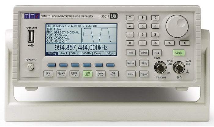
The TG5011A is the single-channel 50MHz model, providing sine and square output across the family's full 1µHz to 50MHz range with square-wave rise and fall times below 8ns.
Frequency range is the primary differentiator: the TG5011A and TG5012A cover 1µHz to 50MHz, while the TG2511A and TG2512A cover 1µHz to 25MHz. The higher-frequency models also offer faster square-wave edges (below 8ns versus below 13ns), a higher PRBS bit rate (to 50Mbps versus 25Mbps), and a wider pulse repetition range, as detailed in the comparison table below.
The second differentiator is channel count: the TG2512A and TG5012A add a second identical output with frequency, amplitude and offset coupling, tracking and an adjustable inter-channel phase offset, whereas the TG2511A and TG5011A are single-channel instruments. Ramp and triangle waveforms extend to 1MHz on the 50MHz models and 500kHz on the 25MHz models.
| Model | Max Frequency | Channels | Square Rise Time |
|---|---|---|---|
| TG2511A | 25MHz | 1 | <13ns |
| TG5011A | 50MHz | 1 | <8ns |
| TG2512A | 25MHz | 2 | <13ns |
| TG5012A | 50MHz | 2 | <8ns |
Additional differences in specifications beyond the few shown above are not listed here — see each model's full specifications below.
| Specification | Value |
|---|---|
| Sine | |
| Frequency Range | 1µHz to 25MHz |
| Frequency Resolution | 1µHz, 14 digits |
| Output Level | 10mVp-p to 10Vp-p into 50Ω |
| Amplitude Flatness (Relative to 1kHz) | <100kHz 0.1dB, <5MHz 0.15dB, <25MHz 0.3dB |
| Harmonic Distortion, DC to 20kHz | ≤1Vp-p: -65dBc; ≥1Vp-p: -65dBc |
| Harmonic Distortion, 20kHz to 100kHz | ≤1Vp-p: -60dBc; ≥1Vp-p: -60dBc |
| Harmonic Distortion, 100kHz to 1MHz | ≤1Vp-p: -45dBc; ≥1Vp-p: -45dBc |
| Harmonic Distortion, 1MHz to 25MHz | ≤1Vp-p: -40dBc; ≥1Vp-p: -35dBc |
| Non-Harmonic Spurii | <–60dBc to 1MHz, <–60dBc + 6dB/octave above 1MHz |
| Phase Noise | -115dBc/Hz, typical (10kHz offset) |
| Square | |
| Frequency Range | 1µHz to 25MHz |
| Resolution | 1µHz, 14 digits |
| Output Level | 10mVp-p to 10Vp-p into 50Ω |
| Rise and Fall Times | <13ns |
| Overshoot | <5% |
| Variable Duty Cycle | 20% to 80% to 20MHz, 0.1% resolution; 40% to 60% to 25MHz, 0.1% resolution |
| Asymmetry | 1% of period + 5ns (@ 50% duty) |
| Jitter (RMS) | 0.5ns + 100 ppm of period |
| Ramp & Triangle | |
| Frequency Range | 1µHz to 500kHz |
| Resolution | 1µHz, 12 digits |
| Output Level | 10mVp-p to 10Vp-p into 50Ω |
| Linearity Error | <0.1% to 30kHz |
| Variable Symmetry | 0.0% to 100.0%, 0.1% resolution. Single key operation of 50% (Triangle) |
| Pulse | |
| Frequency Range | 500µHz to 6.25MHz |
| Resolution | 1µHz, 14 digits |
| Output Level | 10mVp-p to 10Vp-p into 50Ω |
| Overshoot | <5% |
| Jitter | 300ps + 0.01% of period |
| Rise/Fall Times | Rise and Fall times can be independently varied or can be varied together simultaneously. |
| Edge Range | <13ns to 40µs |
| Edge Resolution | 0.1ns for rise/fall time ≤100ns; 1ns for rise/fall >100ns and ≤2µs; 10ns for rise/fall >2µs and ≤40µs |
| Width Range | 20ns to 2000s (20ns minimum for period ≤40s; 200ns minimum for period >40s and ≤400s; 2µs minimum for period >400s) |
| Width Resolution | 10ns for period ≤40s; 100ns for period >40s and ≤400s; 1µs for period >400s |
| Delay Range | 0ns to 2000s |
| Delay Resolution | 10ns for period ≤40s; 100ns for period >40s and ≤400s; 1µs for period >400s |
| PRBS Waveforms | |
| Sequence Length | 7, 9, 11, 15, 20, or 23 stages (127 to 8,388,607 bit length) |
| Bit Rate | 1µbps to 25Mbps |
| Rise/Fall Times | Rise/Fall times can be varied (rise time = fall time). |
| Edge Range | <13ns to 40µs |
| Arbitrary Waveforms | |
| In-built Arbitrary Waveforms | Sinc, Exponential Rise, Logarithmic Rise, DC, Positive and Negative Ramps and Square waveforms are built-in and always present. Additional waveforms are supplied on disc (Cardiac, Gaussian, Exponential Fall, Logarithmic Fall). |
| Frequency Range | 1µHz to 6MHz |
| Resolution | 1µHz, 14 digits |
| Output Level | 10mVp-p to 10Vpp into 50Ω |
| Waveform Size | 2 points to 131072 points (128k) |
| Memory Size | Up to 4 waveforms of up to 64k points, or 2 waveforms of up to 128k points, (or 2 of 64k points plus 1 of 128k points). |
| External Storage | Up to 1,000 waveforms per USB memory stick |
| Vertical Resolution | 14 bits |
| Sampling rate | 125MS/s |
| Output Filter | Selects between 50MHz Elliptic or 20MHz Bessel filter depending on the waveform. |
| Noise | |
| Bandwidth (-3dB) | 20MHz typical |
| Crest Factor | 5.27 (Vp/Vrms) |
| Output Level | 10mVp-p to 10Vpp into 50Ω |
| Sweep | |
| Carrier Waveforms | All standard, PRBS and arbitrary except pulse. |
| Sweep Mode | Linear or logarithmic, triggered or continuous. |
| Sweep Direction | Up, down, up/down or down/up. |
| Sweep Range | From 1µHz to 25MHz subject to carrier waveform. Phase continuous. Independent setting of the start and stop frequency. |
| Sweep Time | 1ms to 500s (6 digit resolution). |
| Marker | Variable during sweep. |
Important: External 10MHz reference clock input accepts 1Vpp to 5Vpp, with a maximum of +5V and a minimum of -1V.
Important: The GPIB (IEEE-488) interface is an option (Option TG-GPIB / option G); when not fitted the instruments retain the standard USB and LAN (LXI) interfaces.
Important: Specifications apply for the temperature range 18°C to 28°C after 30 minutes warm-up, at maximum output into 50Ω unless otherwise stated.
Usage tip: for system installations, the RM200A 19-inch 2U rack mount kit accommodates one or two of these generators.
This is a brand-new, factory-sealed unit, supplied exactly as it arrives from the manufacturer and backed by the full manufacturer warranty. For the exact configuration, available options, included accessories, or current lead time for your application, our Test Architects can confirm the details before you order.
ValueTronics supplies both new and used test and measurement equipment. New units ship factory-sealed, exactly as received from the manufacturer; every used unit is inspected and functionally verified in-house at our 20,000 sq ft secure facility in Elgin, Illinois before it ships. Our Test Architects can help you select the condition, calibration, and configuration that fit your application.
Please review the Manufacturer's Data Sheet to verify published specifications. Feedback on this webpage is always welcome — please reach out to your Test Architect at any time for questions or concerns. Thank you, we truly appreciate you being our customer.
Model No
Aim-TTi
Condition
Factory New
Manufacturer
Aim-TTi
Func_gen_freq
25MHz

30+ Years in Business
Secure Payments
Sell Test Equipments
Knowledgeable Staff
On-site Lab
30+ Years in Business
Secure Payments
Sell Test Equipments
Knowledgeable Staff
On-site Lab
Request A Quote
 Chat Live
 Contact Us
 sales@valuetronics.com