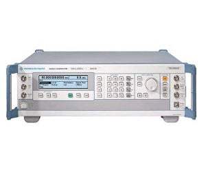
The Rohde & Schwarz SMR50 and SMR60 are microwave signal generators that extend the SMR family with two models reaching up to 50 GHz and 60 GHz respectively. Each is a CW generator with pulse modulation capability, positioned as a high-performance, cost-effective, and reliable microwave source. The standard lower frequency limit is 1 GHz, which can be extended down to 10 MHz with the Frequency Extension option (SMR-B11).
A microwave signal generator produces a known, controllable carrier used to stimulate and characterize a device under test. The SMR50/60 are suited for use as a source for optical components, a source for radar receiver tests, a source for scalar network analysis, and a normal CW source for local-oscillator substitution. Microwave signal generators of this kind are frequently used for calibrating test receivers, a task that calls for a highly accurate and stable output level. The combination of pulse and frequency modulation (FMDC) simulates Doppler effects and chirp signals, while combined SCAN and pulse modulation reproduces the signals occurring in pulse radar applications with a rotating antenna. Their pulse modulation capability also supports the development, production, and maintenance of radar equipment.
ValueTronics stocks and holds its own inventory in a 20,000-square-foot secure warehouse at 1675 Cambridge Drive in Elgin, Illinois. Every used unit is inspected and functionally verified in-house before it ships, while new units leave factory-sealed exactly as received from the manufacturer.
Rohde & Schwarz is a privately held company founded in 1933 in Munich, Germany, by Lothar Rohde and Hermann Schwarz. It has operated continuously under the same name and ownership structure, with no major corporate rebranding or acquisition history.
The Rohde & Schwarz SMR family is extended by two microwave signal generator models, the SMR50 and the SMR60. Both are CW generators with pulse modulation capability and a standard lower frequency limit of 1 GHz, differing principally in their upper frequency reach. Owing to their price/performance ratio, both are positioned for economical microwave test setups, and either can be upgraded over time into an AM/FM signal generator or a synthesized sweep generator through the same flexible options concept.
Each model shares the same architecture: high-precision frequency-response-compensated level control, a standard pulse modulator, digital sweep, 50-setup memory, and SCPI remote control over the IEC/IEEE-bus. The choice between the two is driven mainly by the required top frequency and the corresponding guaranteed output level at that frequency.
Each pre-owned model in the family is presented on its own dedicated product page with condition-matched pricing. Use the comparison below to identify the model whose frequency coverage and output level fit your application, then open that model's page for its full specifications and current pre-owned availability.
The two models differ primarily in upper frequency limit: the SMR50 covers up to 50 GHz and the SMR60 up to 60 GHz, with both extendable down to 10 MHz via the Frequency Extension option (SMR-B11). This difference carries through to the guaranteed output level at the top of each model's range, where the SMR50's ceiling allows correspondingly higher output near 50 GHz than the SMR60 provides near 60 GHz.
Beyond frequency tier, the models are configured identically and accept the same option set, including the OCXO reference, 0.1 Hz resolution, ramp sweep, AM/FM/SCAN modulator, pulse generator, and the RF attenuator that extends the level setting range to -110 dBm. The comparison table that follows lists the per-model frequency and level figures side by side.
| Model | Frequency Range | Max Output Level (top band, without B18) | Frequency Resolution |
|---|---|---|---|
| SMR60 | 1 GHz to 60 GHz | >0 dBm (at 60 GHz) | 1 kHz |
| SMR50 | 1 GHz to 50 GHz | >+3 dBm (at 50 GHz) | 1 kHz |
Additional differences in specifications beyond the few shown above are not listed here — see each model's full specifications below.
| Specification | Value |
|---|---|
| Frequency | |
| R&S SMR60 (without option R&S SMR-B11) | 1 GHz to 60 GHz |
| R&S SMR60 (with option R&S SMR-B11) | 10 MHz to 60 GHz |
| Resolution (without option R&S SMR-B3) | 1 kHz |
| Resolution (with option R&S SMR-B3) | 0.1 Hz |
| Setting time (to within <1 × 10⁻⁶) after IEC/IEEE-bus delimiter | <10 ms + 2 ms/GHz |
| Reference frequency | |
| Aging (after 30 days of operation), Standard / Option R&S SMR-B1 | 1 × 10⁻⁶/year / <1 × 10⁻⁷/year |
| Temperature effect (0°C to +55°C), Standard / Option R&S SMR-B1 | 2 × 10⁻⁶ / <1 × 10⁻¹⁰/°C |
| Warm-up time, Standard / Option R&S SMR-B1 | – / 15 min |
| Output for internal reference, Frequency | 10 MHz |
| Output for internal reference, Level, Vrms (EMF, sinewave) | 1 V |
| Output for internal reference, Source impedance | 50 Ω |
| Input for external reference, Frequency | 10 MHz |
| Input for external reference, Permissible frequency drift | 3 × 10⁻⁶ |
| Input for external reference, Input level, Vrms | 0.1 V to 2 V |
| Input for external reference, Input impedance | 50 Ω |
| Spectral purity | |
| Harmonics, 10 MHz ≤ f ≤30 MHz | <–50 dBc |
| Harmonics, 30 MHz < f ≤20 GHz | <–55 dBc |
| Harmonics, f >20 GHz | <–40 dBc |
| Subharmonics, f ≤20 GHz | <–65 dBc |
| Subharmonics, f >20 GHz | <–30 dBc |
| Nonharmonics (>50 kHz from carrier), f ≤20 GHz | <–60 dBc |
| Nonharmonics (>50 kHz from carrier), 20 GHz < f ≤40 GHz | <–54 dBc |
| Nonharmonics (>50 kHz from carrier), f >40 GHz | <–52 dBc |
| SSB phase noise (f = 10 GHz, 10 kHz from carrier, 1 Hz bandwidth, CW, FM off) | <–83 dBc |
| Residual FM, rms (f = 10 GHz, FM off), 0.3 kHz to 3 kHz | <20 Hz |
| Residual FM, rms (f = 10 GHz, FM off), 0.02 kHz to 23 kHz | <200 Hz |
| Level | |
| Maximum level, 0.01 GHz ≤ f <1 GHz (without B18 / with B18) | >+11 dBm |
| Maximum level, 1 GHz ≤ f <18 GHz (without B18 / with B18) | >+8 dBm / >+7 dBm |
| Maximum level, 18 GHz ≤ f ≤20 GHz (without B18 / with B18) | >+7 dBm / >+5 dBm |
| Maximum level, 20 GHz < f ≤27 GHz (without B18 / with B18) | >+11 dBm / >+9 dBm |
| Maximum level, 27 GHz < f ≤30 GHz (without B18 / with B18) | >+9 dBm / >+7 dBm |
| Maximum level, 30 GHz < f ≤40 GHz (without B18 / with B18) | >+7 dBm / >+5 dBm |
| Maximum level, 40 GHz < f ≤50 GHz (without B18 / with B18) | >+3 dBm / >+0 dBm |
| Maximum level, 50 GHz < f ≤60 GHz (without B18 / with B18) | >0 dBm / >–4 dBm |
| Minimum level of all models (without option R&S SMR-B18) | –20 dBm |
| Minimum level of all models (with option R&S SMR-B18) | –110 dBm |
| Resolution | 0.1 dB or 0.01 dB, selectable |
| Total deviation (level = –4 dBm), f ≤20 GHz | <1 dB |
| Total deviation (level = –4 dBm), 20 GHz < f ≤40 GHz | <1.4 dB |
| Total deviation (level = –4 dBm), f >40 GHz | <1.8 dB |
| Frequency response (level = –4 dBm), f ≤20 GHz | <0.5 dB, typ. <±0.3 dB |
| Frequency response (level = –4 dBm), 20 GHz < f ≤40 GHz | <0.7 dB, typ. <±0.4 dB |
| Frequency response (level = –4 dBm), f >40 GHz | <0.9 dB, typ. <±0.5 dB |
| Impedance | 50 Ω |
| SWR | <2 |
| Setting time after IEC/IEEE-bus delimiter | <10 ms |
| Setting time after IEC/IEEE-bus delimiter (with option R&S SMR-B18, with switching in attenuator) | <25 ms |
| Range for non-interrupting level setting | >16 dB |
| Linear amplitude modulation with option R&S SMR-B5 | |
| Operating modes | internal, external AC/DC |
| Modulation depth | 0% to 100% |
| Setting accuracy (AF = 1 kHz, m <80%) | <4% of reading +1% |
| AM distortion (AF = 1 kHz, m = 60%), f <1 GHz | <3% |
| AM distortion (AF = 1 kHz, m = 60%), f ≥1 GHz | <1% |
| Modulation frequency response (m = 60%), f <1 GHz, DC to 50 kHz | <3 dB |
| Modulation frequency response (m = 60%), f ≥1 GHz, 20 Hz to 20 kHz | <1 dB |
| Modulation frequency response (m = 60%), f ≥1 GHz, DC to 100 kHz | <3 dB |
| Incidental ϕM with AM, peak value (AF = 1 kHz, m = 30%) | <0.4 rad |
| EXT1, EXT2 modulation input, Input voltage Vp for selected modulation depth | 1 V (high/low indication for inaccuracy >3%) |
| Logarithmic amplitude modulation with option R&S SMR-B5 (SCAN AM) | |
| Operating modes | internal, external |
| Dynamic range | >20 dB |
| Sensitivity | ±0.1 dB/V to ±10 dB/V |
| Resolution | 0.01 dB |
| Rise/fall time (10%/90%) | <10 µs |
| EXT1, EXT2 modulation input, Input impedance | 50 Ω/600 Ω or 100 kΩ |
| EXT1, EXT2 modulation input, Input voltage range | –6 V to +6 V |
| Frequency modulation with option R&S SMR-B5 | |
| Operating modes | internal, external AC/DC |
| EXT1, EXT2 modulation input, Input impedance | 50 Ω/600 Ω or 100 kΩ |
| Resolution | 0.1% |
Important: Maximum output level is reduced by up to 2 dB in the 35 C to 55 C temperature range.
Important: Specifications are valid under the following conditions: 30 minutes warm-up time, specified environmental conditions met, calibration cycle adhered to and total calibration performed.
Important: Data designated "typ.", "overrange" or "underrange" are not warranted.
Important: From 10 MHz to 50 MHz, the specified total uncertainty is only valid in the temperature range 15°C to 35°C. The uncertainty outside this temperature range is likely to be higher by max. 0.7 dB.
Important: Options SMR-B11 (Frequency Extension 0.01 GHz to 1 GHz) and SMR-B18 (RF Attenuator 60 GHz) are factory-fitted options.
Recommended pairing: used as a tracking generator with the Rohde & Schwarz FSP Spectrum Analyzer and option FSP-B10, the SMR50/60 provides a scalar network analysis function with wide dynamic range.
This pre-owned unit is inspected and functionally verified in-house before it ships and is backed by our pre-owned warranty. To confirm its exact condition, firmware revision, installed options, or included accessories for your application before ordering, contact our Test Architects.
ValueTronics supplies both new and used test and measurement equipment. New units ship factory-sealed, exactly as received from the manufacturer; every used unit is inspected and functionally verified in-house at our 20,000 sq ft secure facility in Elgin, Illinois before it ships. Our Test Architects can help you select the condition, calibration, and configuration that fit your application.
Please review the Manufacturer's Data Sheet to verify published specifications. Feedback on this webpage is always welcome — please reach out to your Test Architect at any time for questions or concerns. Thank you, we truly appreciate you being our customer.
Model No
Rohde
Condition
Pre-Owned
Manufacturer
Rohde & Schwarz
Rf_gen_freq
1 GHz to 60 GHz
B11
Frequency Extension 0.01 GHz to 1 GHz
B15
RF Attenuator for SMR20/27
B17
RF Attenuator for SMR30/401
B3
Frequency Resolution 0.1 Hz
B5
AM/FM/Scan Modulator

30+ Years in Business
Secure Payments
Sell Test Equipments
Knowledgeable Staff
On-site Lab
30+ Years in Business
Secure Payments
Sell Test Equipments
Knowledgeable Staff
On-site Lab
Request A Quote
 Chat Live
 Contact Us
 sales@valuetronics.com