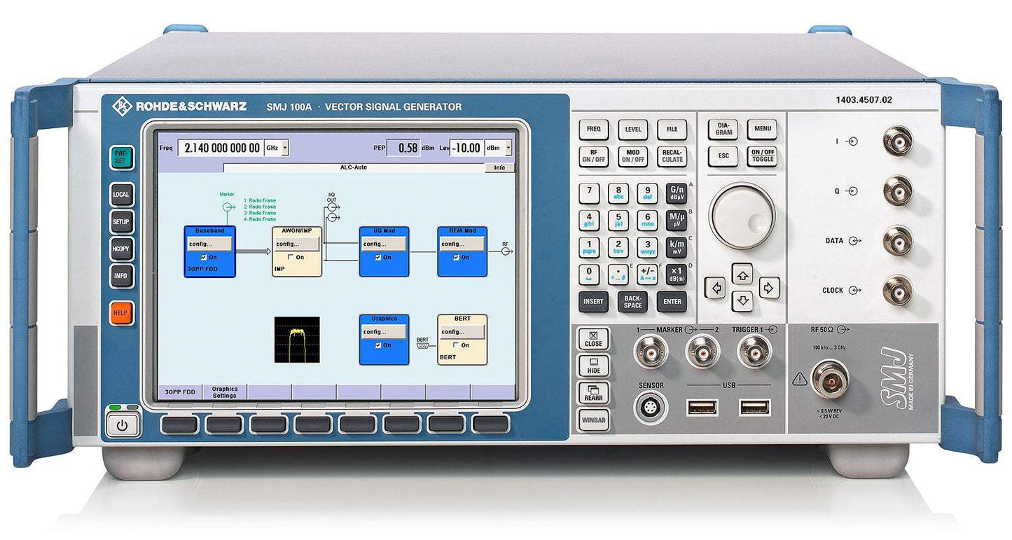
The Rohde & Schwarz SMJ100A is a vector signal generator built around an I/Q modulator with 200 MHz RF bandwidth. It pairs a color SVGA display of 800 x 600 pixels with a graphical user interface that shows the signal flow as a block diagram, a built-in transient recorder for viewing baseband signals, and a context-sensitive help system. A high-stability reference oscillator is included as standard.
The instrument supports generation of a broad span of digital communication standards, including EUTRA/LTE, WiMAX (IEEE 802.16-2004/Corr1-2005, 802.16e-2005, and WiBro), 3GPP FDD with HSDPA and HSUPA, WLAN (IEEE 802.11a, b, g, and n), and GSM/EDGE with modulation changes from slot to slot. Very short frequency and level setting times together with RF List mode and multisegment waveforms suit it to production use.
ValueTronics stocks and holds its own inventory in a 20,000 sq ft secure warehouse at 1675 Cambridge Drive in Elgin, Illinois. Every pre-owned unit is inspected and functionally verified in-house before it ships, while new units ship factory-sealed exactly as received from the manufacturer. Holding the inventory ourselves means the instrument you order is on our shelves and ready to move.
Rohde & Schwarz is a privately held company headquartered in Germany that has operated under the same name since its founding, with no major corporate name changes or acquisitions affecting its brand identity.
| Specification | Value |
|---|---|
| Frequency | |
| Range, underrange | 100 kHz to <300 kHz |
| Range (R&S SMJ-B103) | up to 3 GHz |
| Range (R&S SMJ-B106) | up to 6 GHz |
| Resolution of setting | 0.01 Hz |
| Resolution of synthesis (standard, fundamental frequency range 750 MHz to 1500 MHz) | 5 µHz |
| Setting time (after IEC/IEEE bus delimiter) | <2 ms, typ. 1.5 ms |
| Setting time (in ALC OFF MODE S&H) | <4 ms, typ. 2.5 ms |
| Setting time (after trigger pulse in List mode) | <450 µs, typ. 300 µs |
| Phase offset | adjustable in 0.1° steps |
| Frequency Sweep | |
| Operating modes | digital sweep in discrete steps; automatic, step, single, external single, external step, manual or external trigger, linear or logarithmic spacing |
| Sweep range | full frequency range |
| Step width, linear | full frequency range |
| Step width, logarithmic | 0.01 % to 100 % per step |
| Reference Frequency | |
| Aging (after 30 days of uninterrupted operation) | <1 × 10⁻⁹/day, <1 × 10⁻⁷/year |
| Temperature effect (in operating temperature range) | ±6 × 10⁻⁸ |
| Warm-up time to nominal thermostat temperature | ≤10 min |
| Internal reference output frequency | 10 MHz or external input frequency |
| Internal reference output level | typ. 5 dBm |
| Internal reference output source impedance | 50 Ω |
| External reference input frequency | 5 MHz, 10 MHz or 13 MHz |
| External reference maximum deviation | 3 × 10⁻⁶ |
| External reference input level, limits | ≥−6 dBm, ≤19 dBm (recommended 0 dBm to 19 dBm) |
| External reference input impedance | 50 Ω |
| Level | |
| Setting range | –145 dBm to +20 dBm |
| Maximum level, f ≤ 3 GHz | +13 dBm (PEP) |
| Maximum level, f > 3 GHz | +11 dBm (PEP) |
| Resolution | 0.01 dB |
| Level uncertainty, 1 MHz ≤ f ≤ 3 GHz | <0.5 dB |
| Level uncertainty, f > 3 GHz | <0.9 dB |
| Additional uncertainty with ALC OFF, S&H | <0.2 dB |
| VSWR in 50 Ω system, ALC ON, f ≤ 3 GHz | <1.6, typ. <1.4 |
| VSWR in 50 Ω system, ALC ON, f > 3 GHz | <1.85, typ. <1.6 |
| Setting time, ALC state ON | <2 ms, typ. 1.5 ms |
| Setting time, ALC state OFF | <4 ms, typ. 2.5 ms |
| Setting time, List mode after trigger impulse | <450 µs, typ. 300 µs |
| Uninterrupted level setting range | >20 dB |
| Max permissible RF power, 1 MHz ≤ f ≤ 3 GHz | 50 W |
| Max permissible RF power, f > 3 GHz | 10 W |
| Back-feed, maximum permissible DC voltage | 50 V |
| Spectral Purity | |
| Harmonics, unmodulated, level <8 dBm | <–30 dBc |
| Harmonics, level <13 dBm | typ. <–30 dBc |
| Nonharmonics (>10 kHz offset), 0.3 MHz ≤ f ≤ 200 MHz | <–77 dBc |
| Nonharmonics, 200 MHz < f ≤ 1500 MHz | <–80 dBc |
| Nonharmonics, 1500 MHz < f ≤ 3000 MHz | <–74 dBc |
| Nonharmonics, f > 3000 MHz | <–68 dBc |
| Subharmonics, 1500 MHz < f ≤ 3000 MHz | <–74 dBc |
| Subharmonics, 3000 MHz < f ≤ 6000 MHz | <–50 dBc |
| Wideband noise (carrier offset >10 MHz, 1 Hz BW, CW), 200 MHz < f ≤ 1500 MHz | <–150 dBc (typ. –153 dBc) |
| SSB phase noise (20 kHz offset, 1 Hz BW, unmodulated), f = 1 GHz | <–129 dBc (typ. –133 dBc) |
| SSB phase noise, f = 2 GHz | <–123 dBc (typ. –127 dBc) |
| SSB phase noise, f = 6 GHz | <–113 dBc (typ. –117 dBc) |
| Residual FM (rms at f = 1 GHz), 300 Hz to 3 kHz | <1 Hz |
| Residual FM, 20 Hz to 23 kHz | <4 Hz |
| Residual AM, rms value 20 Hz to 23 kHz | <0.02 % |
| List Mode | |
| Maximum number of channels | 10000 |
| Dwell time | 1 ms to 1 s |
| Resolution | 0.1 ms |
| Internal Modulation Generator | |
| Frequency range | 0.1 Hz to 1 MHz |
| Resolution of setting | 0.1 Hz |
| Output voltage (Vp at LF connector, RL >200 Ω) | 1 mV to 3 V |
| Output impedance | 16 Ω |
| Amplitude Modulation | |
| Operating modes | internal, external AC/DC |
| Modulation depth | 0 % to 100 % |
| Resolution | 0.1 % |
| Modulation frequency range | DC, 20 Hz to 500 kHz |
| Pulse Modulation | |
| Operating modes | external, internal (duty cycle approx. 1:1) |
| ON/OFF ratio | >70 dB |
| Rise/fall time (10 %/90 % of RF amplitude) | typ. 1 µs |
| Pulse repetition frequency | 0 Hz to 100 kHz |
| Frequency Modulation (R&S SMJ-B20 option) | |
| Operating modes | internal, external, internal + external, AC/DC |
| Maximum deviation | rm × 10 MHz |
| FM distortion (fmod = 10 kHz and 1 MHz deviation) | <0.1 % |
| Phase Modulation (R&S SMJ-B20 option) | |
| Maximum deviation, High Deviation φM mode | rm × 20.0 rad |
| Maximum deviation, High Bandwidth φM mode | rm × 1.0 rad |
| I/Q Modulator | |
| Operating modes | external wideband I/Q, internal baseband I/Q |
| I/Q input impedance | 50 Ω |
| Modulation frequency range (I/Q wideband ON) | 100 MHz |
| Carrier leakage (referenced to full-scale input) | <−55 dBc, typ. <−65 dBc |
| Remote Control | |
| Systems | IEC/IEEE bus, IEC 60625 (IEEE 488); Ethernet |
| Command set | SCPI 1999.5 |
Important: Maximum permissible RF power into the output for f > 1 MHz: 50 W (1 MHz <= f <= 3 GHz) and 10 W (f > 3 GHz). Maximum permissible DC back-feed from a >=50 Ohm source: 50 V.
Important: The base unit can only be ordered with an R&S SMJ-B10x frequency option (R&S SMJ-B103 up to 3 GHz or R&S SMJ-B106 up to 6 GHz).
Important: The R&S SMJ-B13 Baseband Main Module must be installed for the I/Q baseband generator options (R&S SMJ-B9/-B10/-B11/-B50/-B51) and for the AWGN (R&S SMJ-K62) option.
Important: Installation of software that is not authorized by Rohde & Schwarz for use on the R&S SMJ100A, or installation of antivirus software, can deteriorate the setting time performance.
Important: The instrument complies with EN 55011 class A emission requirements (industrial environments); it may not be operated in residential, commercial and business areas or in small-size companies unless additional measures are taken to ensure compliance with EN 61000-6-3.
Important: Functional specifications of the digital standard options (R&S SMJ-K40 to -K61) and the external-PC-software options (R&S SMJ-K5/-K6/-K8) are described in the separate Digital Standards data sheet (PD 5213.9434.22); R&S WinIQSIM2 and R&S WinIQSIM each require an external PC.
Usage tip: the optional digital baseband output (R&S SMJ-B18) provides a lossless digital I/Q connection to the digital I/Q input of other Rohde & Schwarz instruments such as the R&S AMU200A baseband signal generator and fading simulator.
This pre-owned unit is inspected and functionally verified in-house before it ships and is backed by our pre-owned warranty. To confirm its exact condition, firmware revision, installed options, or included accessories for your application before ordering, contact our Test Architects.
ValueTronics supplies both new and used test and measurement equipment. New units ship factory-sealed, exactly as received from the manufacturer; every used unit is inspected and functionally verified in-house at our 20,000 sq ft secure facility in Elgin, Illinois before it ships. Our Test Architects can help you select the condition, calibration, and configuration that fit your application.
Please review the Manufacturer's Data Sheet to verify published specifications. Feedback on this webpage is always welcome — please reach out to your Test Architect at any time for questions or concerns. Thank you, we truly appreciate you being our customer.
Model No
Rohde
Condition
Pre-Owned
Manufacturer
Rohde & Schwarz
Rf_gen_freq
100 kHz to 6 GHz

30+ Years in Business
Secure Payments
Sell Test Equipments
Knowledgeable Staff
On-site Lab
30+ Years in Business
Secure Payments
Sell Test Equipments
Knowledgeable Staff
On-site Lab
Request A Quote
 Chat Live
 Contact Us
 sales@valuetronics.com