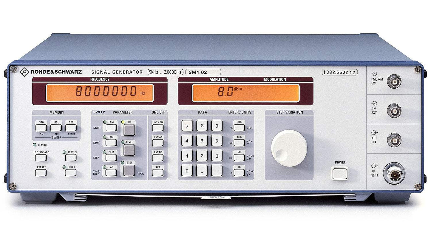
The Rohde & Schwarz SMY is a cost-effective signal generator built for testing AM, FM and ϕM receivers and for component measurements. By concentrating on the main applications of a signal generator and cutting out unnecessary functions, it achieves an outstanding price/performance ratio while retaining comprehensive basic features and strong signal characteristics, making it an economical choice for universal use across lab, production and service environments. The series consists of two models — the SMY01 covering 9 kHz to 1.04 GHz and the SMY02 covering 9 kHz to 2.08 GHz.
A signal generator produces a known, controllable signal used to stimulate a device under test so its response can be measured. The SMY is applied to testing AM, FM and ϕM receivers and to component measurements. Its FM-DC capability, with high accuracy of carrier frequency, supports testing pagers and receivers fitted with digital squelches, and FM-DC deviation of up to 20 MHz allows VCO simulation. An FM bandwidth of 2 MHz suits fast FSK and telemetry applications, while a stereo channel separation of 50 dB with low harmonic distortion supports testing FM stereo receivers.
Every SMY signal generator offered by ValueTronics is stocked and held in our own 20,000-square-foot secure warehouse at 1675 Cambridge Drive in Elgin, Illinois, where we have specialized in new and used test and measurement equipment since 1992. Holding our own inventory lets us ship promptly and stand behind what we sell: each pre-owned unit is inspected and functionally verified in-house, while new units ship factory-sealed exactly as received from the manufacturer.
Rohde & Schwarz was founded in 1933 in Munich, Germany, by Lothar Rohde and Hermann Schwarz. It has remained an independent, privately held company under the Rohde & Schwarz name throughout its history, with no major corporate rebranding or acquisition affecting the brand.
The Rohde & Schwarz SMY series is a single-loop synthesized signal generator line offered in two models that share the same architecture and feature set while differing in upper frequency limit: the SMY01 reaches 1.04 GHz and the SMY02 reaches 2.08 GHz. Both are designed around the main applications of a signal generator — receiver testing and component measurements — for an economical price/performance ratio.
Both models provide 1 Hz frequency resolution, a −140 to +13 dBm standard level range, simultaneous AM/FM/ϕM and pulse modulation, an internal 1 Hz to 500 kHz modulation generator, and an IEC 625 (IEEE 488) interface for automated test systems.
Each model in the SMY series below is its own dedicated product page with pre-owned pricing matched to that specific unit. Select the model that fits your frequency and application requirements, then choose the configuration and condition that suit your budget.
The primary difference across the SMY series is upper frequency coverage: the SMY01 spans 9 kHz to 1.04 GHz while the SMY02 extends to 2.08 GHz. The SMY02's additional 1040–2080 MHz band also supports the highest FM deviation tier of 20 MHz and the widest phase-modulation deviation of 400 rad.
Physical and power-handling figures track the frequency range as well: maximum permissible RF power is 30 W on the SMY01 versus 50 W on the SMY02, depth is 350 mm versus 460 mm, and a fully equipped unit weighs 12 kg versus 13 kg. The comparison table below lists these model-specific values side by side.
| Model | Frequency Range | Max RF Power | Weight |
|---|---|---|---|
| SMY02 | 9 kHz to 2.08 GHz | 50 W | 13 kg |
| SMY01 | 9 kHz to 1.04 GHz | 30 W | 12 kg |
Additional differences in specifications beyond the few shown above are not listed here — see each model's full specifications below.
| Specification | Value |
|---|---|
| Frequency | |
| Range | 9 kHz to 2.08 GHz |
| Underranging | down to 5 kHz (without guarantee of specs) |
| Resolution | 1 Hz |
| Setting time (to within <1 x 10⁻⁷ for f >65 MHz or <70 Hz for f <65 MHz) | <60 ms |
| Reference Frequency | |
| Aging (after 30 days of operation), standard | 1 x 10⁻⁶/year |
| Aging, option SMY-B1 | <1 x 10⁻⁹/day |
| Temperature effect (0 to 55°C), standard | 2 x 10⁻⁶ |
| Temperature effect, option SMY-B1 | <5 x 10⁻⁸ |
| Warmup time, option SMY-B1 | 10 min |
| Output for internal reference, frequency | 10 MHz |
| Output for internal reference, level Vrms (EMF, sinewave) | 1 V at 50 Ω |
| Input for external reference | 5 or 10 MHz ±5 x 10⁻⁶ |
| Input level (Vrms) | 0.2 to 2 V at 200 Ω |
| Spectral Purity | |
| Spurious signals — Harmonics | <−30 dBc for levels <10 dBm; <−25 dBc for levels <16 dBm¹⁾ |
| Subharmonics | none (f >1.04 GHz: <−40 dBc) |
| Nonharmonics at >5 kHz from carrier | <−70 dBc (f >1.04 GHz: <−64 dBc) |
| Broadband noise with CW, carrier offset >1 MHz, 1 Hz bandwidth, f≥65 MHz | <−140 dBc |
| SSB phase noise at 20 kHz from carrier, 1 Hz bandwidth, CW, f <65 MHz | <−114 dBc |
| SSB phase noise, 100 MHz / 500 MHz | <−132 dBc / <−120 dBc |
| SSB phase noise, 1 GHz / 2 GHz | <−114 dBc / <−108 dBc |
| Residual FM, rms, <1% of max. deviation, f=1 GHz, 0.3 to 3 kHz (CCITT) | <10 Hz (0.03 to 20 kHz: <20 Hz) |
| Residual AM, rms (0.03 to 20 kHz) | <0.02% |
| Level | |
| Range | −140 to +13 dBm; −134 to +19 dBm¹⁾ |
| Overranging (without guarantee of specs) | up to +19 dBm; −140 to +25 dBm¹⁾ |
| Resolution | 0.1 dB |
| Accuracy for levels >−127 dBm | ±1 dB (f >1.04 GHz: ±1.5 dB) |
| Frequency response at 0 dBm | 1 dB, typ. 0.3 dB |
| Characteristic impedance | 50 Ω |
| VSWR | <1.5 (f >1.04 GHz: <1.8) |
| Setting time (IEC/IEEE bus) | <25 ms (<10 ms with electronic level setting) |
| Non-interrupting level setting | 0 to −20 dB |
| Overload protection | protects the instrument against externally applied RF power and DC voltage (50 Ω source) |
| Max. permissible RF power | 50 W |
| Max. permissible DC voltage | 35 V |
| Max. pulse load (pulse width <10 µs) | 1 mWs or 150 V (peak) |
| Modulation | |
| Simultaneous modulation | any combination of AM, FM (ϕM) and pulse modulation |
| Amplitude Modulation | |
| Source | internal, external AC/DC |
| Modulation depth | 0 to 100% |
| Resolution | 0.1% |
| Setting error at 1 kHz (m <80%) | <4% of reading ±1% |
| AM distortion at 1 kHz, m=30% | <1%; 3%¹⁾ |
| AM distortion at 1 kHz, m=80% | <2%; 5%¹⁾ |
| Modulation frequency response (m=60%), 30 Hz (DC) to 10 kHz | 0.4 dB |
| Modulation frequency response (m=60%), 10 Hz (DC) to 50 kHz | 3 dB |
| Incidental ϕM at AM (30%), AF=1 kHz | <0.2 rad; <0.4 rad at f >1.04 GHz |
| Frequency Modulation | |
| Source | internal, external AC/DC |
| Max. deviation, carrier frequency <65 MHz | 10 MHz |
| Max. deviation, 65 to 130 MHz | 1.25 MHz |
| Max. deviation, 130 to 260 MHz | 2.5 MHz |
| Max. deviation, 260 to 520 MHz | 5 MHz |
| Max. deviation, 520 to 1040 MHz | 10 MHz |
| Max. deviation, 1040 to 2080 MHz | 20 MHz |
| Resolution | <1%, min. 10 Hz |
| Setting error at AF=1 kHz | <3% of reading + 20 Hz |
| FM distortion at AF=1 kHz and 3% of max. deviation | <0.3%, typ. 0.1% |
| Modulation frequency response, 10 Hz (DC) to 2 MHz | 3 dB, typ. 1 dB |
| Incidental AM at AF=1 kHz, f >1 MHz, 40 kHz deviation | <0.1% |
| Stereo Modulation (40 kHz deviation, AF=1 kHz) | |
| Crosstalk attenuation | >50 dB |
| S/N ratio, unweighted | >76 dB |
| S/N ratio, weighted | >70 dB |
| Distortion | typ. 0.1% |
| Carrier frequency offset with FM-DC | <1 Hz + 0.1% of deviation |
| Phase Modulation | |
| Source | internal, external AC |
| Max. deviation, carrier frequency <65 MHz | 200 rad |
| Max. deviation, 65 to 130 MHz | 25 rad |
| Max. deviation, 130 to 260 MHz | 50 rad |
| Max. deviation, 260 to 520 MHz | 100 rad |
| Max. deviation, 520 to 1040 MHz | 200 rad |
| Max. deviation, 1040 to 2080 MHz | 400 rad |
| Resolution | <1%, min. 0.01 rad |
| Setting error at AF=1 kHz | <5% of reading + 0.02 rad |
| Distortion at AF=1 kHz and 50% of max. deviation | <0.5% (typ. 0.2%) |
| Modulation frequency response, 20 Hz to 20 kHz | <3 dB (typ. 1 dB) |
| Pulse Modulation | |
| Source | external |
Important: Overload protection guards the instrument against externally applied RF power and DC voltage from a 50 Ω source. Maximum permissible DC voltage: 35 V; maximum permissible RF power: 30 W (SMY02: 50 W).
Important: The High Output Power option (SMY-B40) is to be retrofitted by authorized service centers only.
Important: Due to its few maximally-stable reference components and control loops that compensate aging and drift, the SMY requires calibration only at intervals of 3 years.
This pre-owned unit is inspected and functionally verified in-house before it ships and is backed by our pre-owned warranty. To confirm its exact condition, firmware revision, installed options, or included accessories for your application before ordering, contact our Test Architects.
ValueTronics supplies both new and used test and measurement equipment. New units ship factory-sealed, exactly as received from the manufacturer; every used unit is inspected and functionally verified in-house at our 20,000 sq ft secure facility in Elgin, Illinois before it ships. Our Test Architects can help you select the condition, calibration, and configuration that fit your application.
Please review the Manufacturer's Data Sheet to verify published specifications. Feedback on this webpage is always welcome — please reach out to your Test Architect at any time for questions or concerns. Thank you, we truly appreciate you being our customer.
Model No
Rohde
Condition
Pre-Owned
Manufacturer
Rohde & Schwarz
Rf_gen_freq
9 kHz to 2.08 GHz

30+ Years in Business
Secure Payments
Sell Test Equipments
Knowledgeable Staff
On-site Lab
30+ Years in Business
Secure Payments
Sell Test Equipments
Knowledgeable Staff
On-site Lab
Request A Quote
 Chat Live
 Contact Us
 sales@valuetronics.com